Preventing and control of SF6 emissions from high voltage gas insulated switchgear has always been a challenge.
You can find more information about important points for SF6 gas leakage on-site test for high voltage switchgear here.
Sulphur Hexafluoride (SF6) emissions from electrical equipment have been a key area of concern in achieving greenhouse gas emission reduction targets. This is due to the significant impact of SF6 emissions on global warming. The lifetime of SF6 in the atmosphere is 3,200 years, and its Global Warming Potential (GWP) is equal to 23,900 (i.e., the impact of 1kg of SF6 is equivalent to 23, 900 kg of CO2).
In the year 2000 SF6 emissions from the production of medium and high voltage (HV) electrical transmission and distribution equipment were estimated about 10 Mt CO2-eq, mainly located in Europe and Japan.
SF6 Gas emissions in the atmosphere and global decisions to prevent emissions:
In the march towards a net zero world, it is well-known that the power industry has made huge shifts from hydrocarbon power generation to renewable and green energy sources, however maybe less well documented is the issue of control of another environmental risk within the industry.
Sulfur hexafluoride (SF6) has been used as an insulating and arc-quenching medium in high voltage switchgear since the 1950s.
Whilst primarily used in switchgear applications due to its inert nature and arc-quenching properties, the
chemical composition of SF6 also lends itself to other uses, for example, in the medical field as a contrast agent in ultrasound imaging, as a thermal and acoustic insulating medium in double glazing, and at one point even as the ‘air’ filler in the sole of a well-known brand of sports shoes.
Attempts have been made to limit the use and emissions of SF 6 since the Kyoto protocol was adopted in
1997 and significant strides have been made in recent years in the electrical transmission industry to
develop alternative equipment and insulating mediums.
Dry air insulation can now be used for voltages up to 420kV in non-switching gas-insulated busbars (GIB) and vacuum interrupters have been developed for use up to 145kV. Similarly, alternate gas technology such as g 3 (g cubed) can be used for voltages up to 420kV in non-switching gas-insulated busbars (GIB).
Alternate gas circuit breakers are available for voltages up to 145kV and it is expected a scalable 245kV g 3 circuit breakers will be available by 2025.
Nonetheless, a normal operating lifetime of 25 years or more coupled with the fact that still today almost all of the high voltage GIS manufactured are SF6 filled means that the impact of SF 6 on the environment is an issue to be managed now and for the decades to come.
Additionally, with the advances made in equipment lifetime extension through predictive maintenance, the environmental cost of a replacement should also be taken into consideration and a gas leak on otherwise healthy equipment need not necessarily be a reason for replacement.
SF6 Gas leakage in GIS systems and its prevention methods:
Gas leaks develop on high voltage GIS for several reasons – manufacturing defects, design faults, the impact of weather on outdoor equipment, incorrect installation, aging of gaskets and seals, etc., and due to the criticality of many substations, the ability to shut down the equipment to affect a repair is often restricted.
This can result in a continuous top-up of leaking gas zones with an equivalent constant emission of SF6 gas into the atmosphere.
In several regions around the world governments and regulators impose both stiff penalties for such emissions as well as incentives for a managed reduction.
A demand, therefore, exists for an effective means of solving gas leaks and preventing the emission of SF6
from aging equipment beyond the operationally disruptive and time-consuming conventional OEM method of the shutdown, degassing, dismantling, and repair.
Several methods have been tried over recent years with limited degrees of success, often reducing but not solving the leak and restricting future access to the affected component in the process.
1. Adhesive coatings or industrial wraps fail to stop leaks when applied directly onto the leaking area under pressure. Even with a reduction in gas pressure and the associated operational disruption during the installation and curing process, the success rate tends to be limited and short-term.
2. Epoxy encasings can divert the leak while the epoxy cures avoiding the issue encountered in point 1 successfully stopping the leak. The limitations of this method include being generally restricted to flange locations and the finished product solidifies onto the equipment restricting future access if required. Removal is time-consuming and extreme care has to be taken not to damage the encased flange and bolts in the process.
MG Eco Solutions (Master Grid Group) company method to prevent SF6 gas leaks and emissions:
MG Eco Solutions (Master Grid Group) have developed a unique system that addresses these major limitations of operational disruption, a restricted leak location application, and an inconsistent success rate.
Developed for applications in the harsh environment of French coastal nuclear power stations MG Eco Solutions also have a track record in tropical climates.
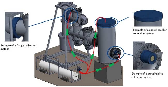
In photo 1 you can see MG Eco Solutions company solutions sleakbag collection system for an high voltage gas insulated switchgear

Photo 1: Schematic of MG Eco Solutions Sleakbag collection system, collecting multiple leaks in one system
Through a process of reverse engineering MG Eco Solutions is able to design and manufacture containment systems to address gas leaks in almost any location on any brand of GIS.
Employing a combination of a new gas tight polymer seal and O ring, the gas leak is contained within the solution with no attempt to plug the leak or fill the void with resin.
The containment system can be considered a permanent solution, but it is also removable should access
be required with some components able to be re-used in other locations.
What makes MG Eco Solutions all the more versatile is their ability to provide a collection system where a permanent containment system is not possible (for example on a leaking bursting disc or bellows unit).
This solution follows the same principle of reverse engineering to ensure a precise interface with the leaking equipment, but rather than containing the leak at working pressure, the gas is piped off to a collection system preventing those harmful emissions of SF6 to the atmosphere.
The long term goal for the power industry towards a net zero world is the complete replacement of SF6
filled equipment. This goal requires time, investment and continuing advancements in alternative technologies.
In the meantime the management of the considerable installed base of GIS and the containment and collection of SF 6 gas leaks is a critical contribution to this goal.

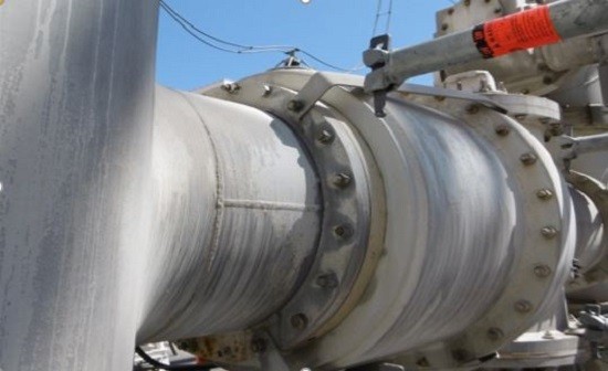
Photo 2: GIS Leaking flange before
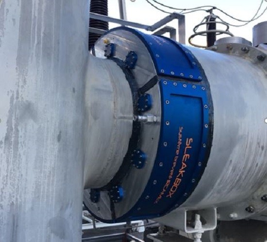
In photo 2,3 you can see MG Eco Solutions (Master Grid Group) companys sealing system for a leakage flange leak on high voltage gas insulated switchgear before and after solution .

Photo 3: GIS after gas leak is contained
We thank Mr. Andrew Morrow from the MG Eco Solutions company for sending and correcting this content.


