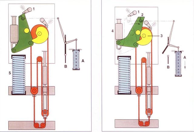
Damping unit equipment used for absorbing motion in high voltage circuit breakers.
You can see damping units in different applications In cars, trains, airplanes, buildings (for earthquakes), etc. Some times a need for absorbing vibration or absorbing impact. Circuit Breakers generally use an oil-damping unit. This oil is a kind of hydraulic oil.
Oil damping unit working with flow mechanics. Oil flow is similar to the current flow in the circuit. Oil pressure looks like voltage. Oil flowing looks current. And the pipe looks like cable. The big diameter hole has less oil resistance and the small diameter hole has much oil resistance.
You can see the oil flow channel in the damping unit inside in Photo-3.
So oil flow resistance changes from less to much. Controlling damping with your hand is not suitable. You don’t catch any faulty situation. It works only with fast operation (Real operation velocity).
How many Damping Units are in high-voltage circuit breakers?
(Hitachi and ABB )FSA1, BLK222, MSD1 mechanism series, (GE, Alstom, and Areva) CRR, FK mechanism series, (Siemens) FA2S mechanisms series contain only one damping unit and it works opening operation. Hitachi and ABB BLG mechanism and Siemens old FA mechanism series contain opening and closing damping units. You have to use a damping unit opening operation.
Opening speed is faster than closing speed. And opening spring directly connected main rod. (Closing spring not connected to a main rod or opening spring. The closing spring only pushes the opening spring linkage. ) So opening operation is more powerful than closing. (More faster and more massive)
The closing spring links to the closing cam disk. The closing cam disk turns one circle in charging closing spring + closing operation=360° (except BLG mechanism).
End of closing operation. Closing cam disk charged the opening spring and operated CB to close position. And ıts mass is only closing the cam disk. (There is no link anywhere). The last part of the Cam disk energy can be charged again closing the spring. For this reason, the designer can design a high voltage circuit breaker without closing the damping unit.
How does the damping unit in high voltage circuit breakers?
In the example (Picture-1) you can see motion starts around 20 ms. After 50ms CB is a safety zone but you must absorb this opening energy. For protection of the mechanism, you can use a damping unit.
Always damping units link are in the hole. The hole provides transmitted movement to the damping zone at different time zones. In the first time zone, CB extinguishes the arc and withstands TRV and Nominal Voltage. The second time zone in opening speed is a decrease in velocity.
As you understand from the above paragraph, CB extinguishes the arc and withstands TRV and nominal voltage without damping the unit.
The damping unit protects the mechanism against the mechanism opening movement shock
This paper examines all periods of damping unit maintenance. With this case study, you can easily understand the effect of motion analysis and how you intervene in the damping unit.
Brand: Alstom
Type: S1-170 F3
Production Year:2000
The test results of the above-mentioned circuit breaker on 17.02.2023 are summarised in Table 1 below:
| Measurements | A fazı | B Fazı | C Fazı |
| Contact Resistance (µΩ) | 38 | 39 | 36 |
| Open1 (ms.) | 36,4 | 37,2 | 36,4 |
| Open2 (ms.) | 36,5 | 36,9 | 36,6 |
| Open Total Travel(°) | 62 | 63,21 | 61,89 |
| Open Over Travel(°) | 0,99 | 0,84 | 0,46 |
| Open Rebound(°) | 6,43 | 9,96 | 4,95 |
| Open Contact Wipe (°) | 19,54 | 22,99 | 19,18 |
| Damping Movement | Anormal | Anormal | Anormal |
Table 1: Test Results Before Intervention
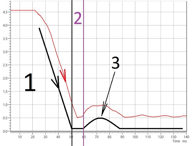
Picture-1 A Phase Open Movement in high voltage circuit breaker
The Picture -1 is taken as A phase opening movement. The black line is drawn for a good understanding of the damping zone problem.
The picture is divided into 3 parts by references to the black line.
The first part of the picture movement is seen as linear (Up to 50ms).
The second part of the picture movement is seen as horizontal (From 50ms to 60ms). So we can understand there is no resistance to movement velocity. A third of part of the picture there will see a huge rebound.
After the test result, the mechanism box was investigated. There was a huge oil on the bottom of the mechanism box. The oil color was yellow. (Photo-1).

Photo-1 Hydraulic oil residues accumulated under the mechanism box
The team determined that the damping unit was faulty and decided to remove the damping unit.
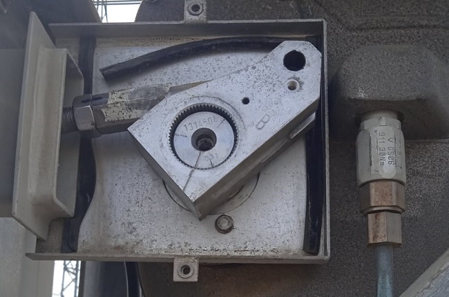
Photo-2 Link between mechanism box and pole in high voltage circuit breaker
The following steps were followed to remove the damping unit.
- All springs are discharged.
- The CB was moved to the open position.
- The pin between the arm coming from the mechanism and the high voltage circuit breaker is removed. (Photo-2)
- The pin on the fixed side (mechanism box) of the opening damping unit was removed.
- No physical damage was detected on the metallic part of the damping unit.
- All hardened gaskets and seals inside the damper have been replaced with new ones.
- 46 numbers of hydraulic oils have been selected for the renovation of the damper.
- Two oil levels were selected. One is phase A, and the other one is phases B and C(Photo-3)
- In the moving part of the damping unit, a chemical stabilizer (medium-level Loctite) was applied to the threaded part that makes the mechanism connection in the moving part of the damping unit, and the dismantled bearing was installed. (It was necessary to heat the relevant part while dismantling).
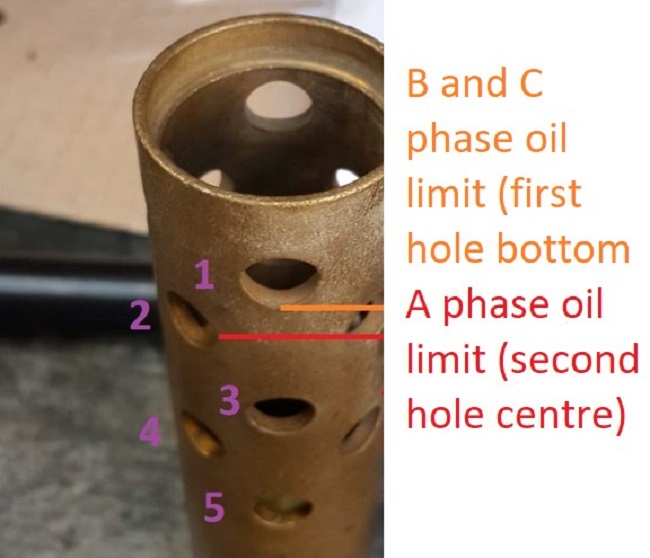
Photo-3 Oil flowing channels of damping unit. (inside of damping unit)
After renovation, the result on the below was taken. (Table 2):
| Measurements | A Phase | B Phase | C Phase |
| Contact Resistance (µΩ) | 37,74 | 35,88 | 35,58 |
| Open1 (ms.) | 36,9 | 37,6 | 36,8 |
| Open2 (ms.) | 62,34 | 62,14 | 61,7 |
| Open Total Travel(°) | 62,45 | 62,18 | 61,71 |
| Open Over Travel(°) | 0,38 | 0,42 | 0,23 |
| Open Rebound(°) | 0 | 0,21 | 0,16 |
| Open Contact Wipe (°) | 20,04 | 22,3 | 19,33 |
| Damping Movement | Normal | Normal | Normal |
Table 2 After renovation test results
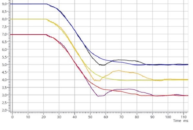
Picture-2 Graphs all phases (Before and after)
In the test results, the purple to red curve for phase A in the first picture, for phase B from orange to yellow curve, and from black to blue curve for phase C. (Rebounds have disappeared) After about 50 operations (C + O is one operation), no drops of oil could be seen from the base of the mechanism (the most important item).
When the previous test results (Table-1 and 2) and graphs (Picture-1 and 2) are analyzed, it is seen that the difference caused by the damping zone in Picture-1 is corrected in Picture-2 and the difference in the A phase Opening Rebound in Table-1 is also corrected in Table 2.
Conclusions:
- Provided that the renovation test results (rebound on opening) are favorable, the procedure summarised above can be applied to all dampers leaking oil from the seal.
- If the opening spring is located in the mechanism, a special apparatus may be required to break the last pressure of the opening spring. In this high voltage circuit breaker and GL series circuit breaker, it is sufficient to remove the arm which between the mechanism box and the pole.
- It was confirmed that the oil leakage was not reflected in the test results when it first occurred by adding different levels of oil to phases A and B-C.
- The main reason for putting different oils in phases A and B-C is to confirm which one is correct. No unfavorable situation and test results were detected in two different levels. The reason for this is that the gap created by the missing oil amount due to the lowering of the pusher arm in the opening damper went to the area where the damper was used and the oil level showed the same effect.
- Number 46 hydraulic oil is learned to be a type of oil used in car shock absorbers. It is thought to be used in dampers.
- Don’t forget the sign of the damping unit. False pick up the daming unit pieces. It caused different total strokes.
- There must be at least one fixed vise to perform these operations.
- You can get help from car shock absorber repairmen.


