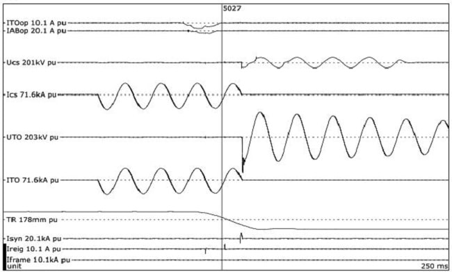
Circuit breaker switching terminology can be understood by considering an actual event.
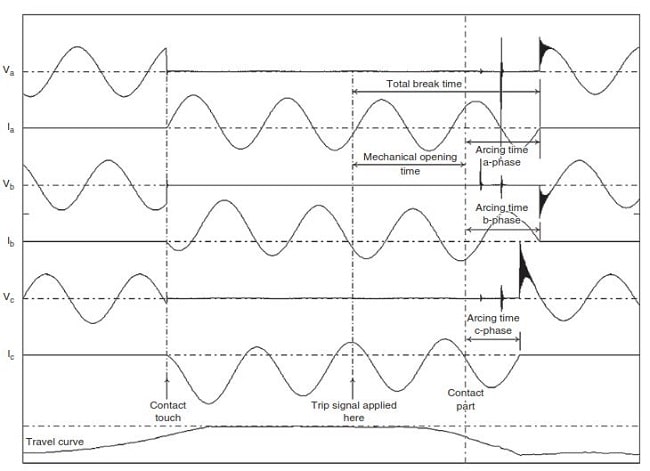
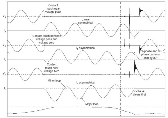
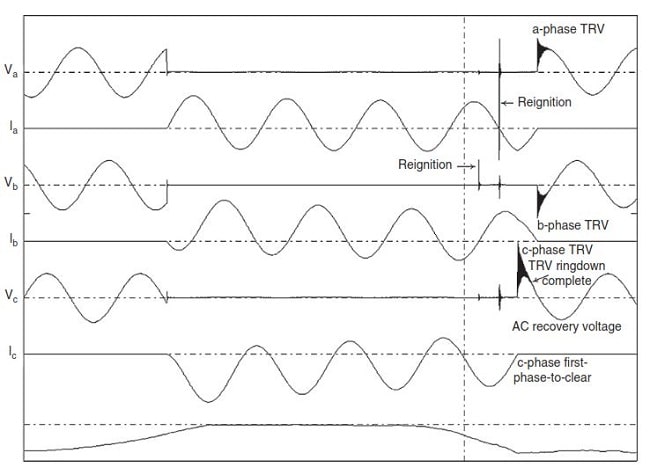
Figures 1 to 3 show the trace of a close-open (CO) three-phase unearthed fault current test on a vacuum circuit breaker (trace courtesy of KEMA).
Taking each figure in turn, the terminology is as follows:
Circuit breaker switching timing-related quantities:
It can be seen carefully in figure 1 that:
- The circuit breaker is initially open, and a close signal is applied to the close coil to initiate the closing.
- After a short electrical delay time, the moving contact starts in motion (travel curve at the bottom of the trace) and makes contact with the circuit breaker fixed contact. This instant is referred to as contact touch or contact made. In practice, the actual electrical making of the circuit may precede mechanical contact due to a prestrike between the contacts. The time between the application of the close signal and contact touch is the mechanical closing time of the circuit breaker.
- The circuit breaker is now closed and carrying fault current. A trip signal is applied to the trip coil initiating opening, also referred to as tripping, of the circuit breaker. After a short electrical time delay, the moving contact is set in motion and mechanical separation of the fixed and moving contacts occurs. This instant is referred to as contact part, contact parting, or contact separation. The time between the application of the trip signal and the contact part is the mechanical opening time.
- An arc is drawn between the contacts and current interruption attempts are made as the zero crossings occur, first on the b-phase, then on the a-phase, and successfully on the c-phase.
c-phase is thus the first pole to clear with an arcing time – the time between the contact part and current interruption – of about one half-cycle. The interrupting time, also referred to as the break time, on the c-phase is the mechanical opening time plus the arcing time.
- At current interruption in the c-phase, the currents in the a-phase and b-phase become equal in magnitude and opposite in polarity by means of a 30 shift, a shortened half-cycle in the former phase, and a longer half-cycle in the latter. The total break time is the mechanical opening time plus the maximum arcing occurring in these two phases.

Figure1: Circuit breaker switching timing-related quantities
Circuit breaker switching current-related quantities:
It can be seen carefully in figure 2 that:
- For a fault initiated at a voltage peak, the current will be symmetrical. Symmetrical means that each half-cycle of the current also referred to as a loop of current, will be identical to the preceding half-cycle of current. The current in a-phase is near symmetrical as a result of fault initiation just prior to the voltage peak.
- The currents in the b-phase and c-phase are asymmetrical and consist of long and short loops of current referred to as major loops and minor loops, respectively.
Maximum asymmetry occurs when the fault is initiated at a voltage zero crossing.

Figure2: Circuit breaker switching current-related quantities
Circuit breaker switching voltage-related quantities:
It can be seen carefully in figure 3 that:
- Current zeros occur every 60 and the pole closest to a zero after the contact part will make the first attempt to interrupt the current. The b-phase pole which is the closest to the first zero makes the attempt to interrupt the current but reignites because the contacts are too close to withstand the TRV. The a-phase pole in turn also makes an attempt but reignites followed by successful interruption on the c-phase, i.e. recovering against the TRV and AC recovery voltage.
- The TRV is a transient oscillation as the voltage on the source side of the circuit breaker recovers to the pre-fault system voltage. The TRV oscillates around the AC recovery voltage, its aiming point, or axis of oscillation, reaching a peak value depending on the damping in the circuit. As the trace shows, the TRV rings down within a power frequency quarter cycle. The first pole to clear is exposed to the highest TRV.
- a-phase and b-phase poles clear 90 later; each with its own TRV of lower magnitude than for c-phase and of opposite polarities. The AC recovery voltage is the line voltage and is shared by both poles.

Figure3: Circuit breaker switching voltage-related quantities


