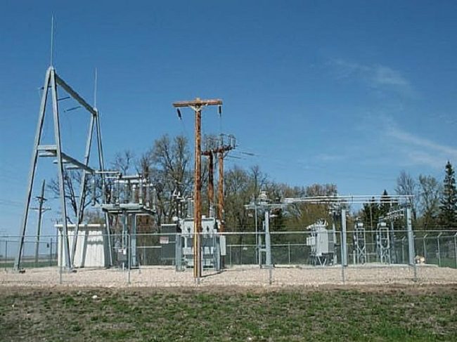
Controlled Switching Device in medium voltage range:
More than 30 years ago, the first Controlled Switching Devices were deployed to mitigate switching transients resulting from the operation of high voltage circuit breakers connected to shunt reactors and capacitor banks. Later studies led to the use of Controlled Switching Devices technology for both transmission lines and power transformer applications. However, in most cases, Controlled Switching Dioceses were controlling the optimum switching moment on a phase-by-phase basis using independent pole-operated circuit breakers (IPO). More recently, the fast-growing worldwide energy demand has created a need to deploy renewable energy resources connected to medium voltage distribution grids (medium voltage) rather than on HV transmission systems.
You can find more about control switching conditions in high voltage grids here.
As for high voltage systems, the medium voltage grid operators were rapidly confronted with the necessity of addressing excessive voltage dip issues resulting from uncontrolled power transformer energization inrush currents.
But the fact is that medium voltage switchgear mostly consists of a three-pole operated apparatus (simultaneous pole operation) thus forcing a major breakthrough in control switching device technology: the mitigation of power transformer energization inrush current using standard switches with simultaneous pole operation. Nowadays, this technology is not only used in wind farms and photovoltaic solar plants, but also in industrial installations, in transportation, etc., where energizing medium voltage and high voltage power transformers without inrush current mitigation can be problematic.
Inrush current in medium voltage transformers:
The maximum inrush current produced by the transformer energization is increased by the presence of residual flux in its core: the higher the maximum core residual flux, the higher inrush current may result from the random energization of the transformer.
The controlled energization of power transformers reduces their inrush currents at all times. In high voltage applications, controlled switching of circuit breakers with independent pole operation would mitigate the inrush current to negligible orders of magnitude, effectively eliminating the voltage dips on the grid. In medium voltage applications, controlled switching technology also provides the best inrush current mitigation using switchgear with simultaneous pole operation. While the presence of high residual flux in the core increases the maximum random energization inrush current of power transformers, the use of CSD technology has the opposite effect. As a result, high core residual flux results in lower energization inrush currents, and potentially, their complete elimination.
The relationship between residual flux and transformer inrush current has been verified using data collected in the field during the commissioning of control switching devices on circuit breakers and switchgear with simultaneous pole operation. In most applications, a CSD would provide a 3:1 inrush current mitigation compared to random energization of transformers.
Inrush current mitigation methods with gang operated circuit breaker:
The next figure illustrates the controlled switching inrush current mitigation concept applied to power transformers. When the phase R of a demagnetized power transformer is energized at zero crossing of the voltage (left, in Figure 1), it pushes the transformer core deeply into saturation, adding 2 p.u. of flux in its core. However, when the transformer is energized at the positive voltage crest, this positive quarter cycle only adds 1 p.u. of flux into the core. The voltage then starts being negative, thus decreasing the flux in the core: since the transformer saturation limit is not reached, the core does not saturate, consequently eliminating the occurrence of inrush current. This corresponds to the energized steady state of the transformer, where the core flux lags the voltage by 90°.
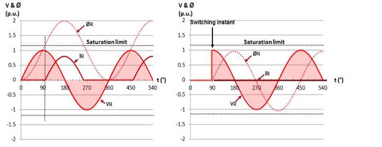
Figure 1: Influence of the energization moment on the inrush current
The situation is more complex when using a 3-phase switch with simultaneous pole operation. As a matter of fact, choosing the energization instant that minimizes the inrush current on one phase is detrimental to the other two phases. This is illustrated in Figure 2 where solving phase R inrush current on the demagnetized transformer (left) is detrimental to phases Y and B (right).
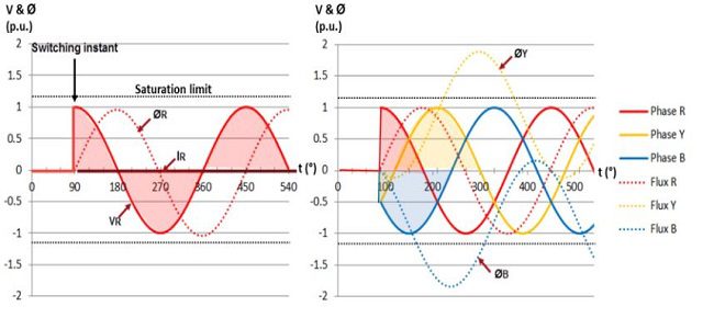
Figure 2: Simultaneous energization of transformer phases
As explained earlier, the residual flux pattern in a power transformer is the result of its previous de-energization.
When a transformer is re-energized, the dynamic flux induced by the applied voltage is added to the residual flux or subtracted from it according to the polarity of the applied voltage. According to the basics of controlled switching principles, the optimum energization moment of a power transformer phase occurs when the induced prospective flux matches the existing residual flux (Figure 3, left). For example, in the presence of a positive flux, applying a negative voltage would first decrease the core flux to zero at the negative voltage crest and immediately reach the permanent regime of the transformer without saturating its core. Conversely (Figure 3, right), energizing the phase at a positive zero crossing of the voltage would add 2 p.u. of positive flux into the core above the existing 0.5 p.u. residual flux. The power transformer core would be pushed into deep saturation with excessive inrush current. The presence of residual flux is therefore increasing the maximum inrush current when the transformer energization is uncontrolled.
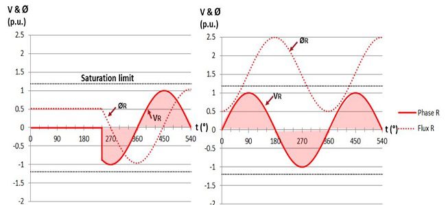
Figure 3: Influence of the residual flux on the power transformer energization
When there is residual flux in the transformer core, the situation with a Gang operated circuit breaker the situation is even more complex. The optimum energization instant must take into consideration the simultaneous operation of the 3 phases according to the magnitude and polarity of the residual flux. However, for each possible residual flux pattern, there is always an optimum energization instant that results in minimum transformer saturation (Figure 4). In the next example, the residual flux pattern is 0, -0.5, +0.5 p.u. respectively in phases R, Y, and B. Energising the power transformer at 90° (crest voltage of phase R) result in the minimum saturation of the phases. However, closing the blue phase at positive zero crossing of the voltage (240°) would cause the worst inrush current, which would be 6.5 times higher than the optimum switching instant calculated by a CSD.
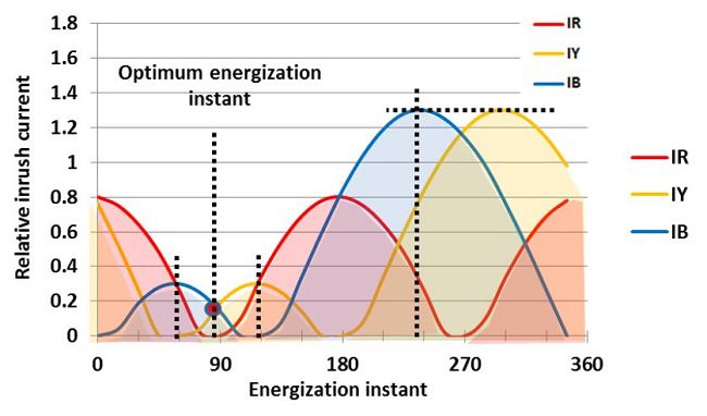
Figure 4: Relative inrush current according to the transformer energization instant (°)
When not controlling the energization of a power transformer, the worst possible inrush current will always appear on the phase with the highest residual flux. A control switching device minimizes the energization inrush current by computing the optimum pole closing instant based on the residual flux pattern. As a result, the inrush current can be totally eliminated in the presence of specific high residual flux patterns.
Figure 5 illustrates the theoretical relative inrush current during energization as a function of the highest of the three residual fluxes measured in the transformer (saturation knee of 1.2 p.u.). The peak inrush current is normalized to the maximum energization current of the demagnetized core. When the core residual flux is high (horizontal axis), the control switching device eliminates the inrush current as the transformer is not pushed into saturation (bottom area of the blue line). Conversely, energizing the power transformer at a random moment can saturate the transformer up to the maximum value (red line), leading to excessive inrush current and the consequential voltage dips on the grid. This diagram, therefore, demonstrates the efficiency of inrush current mitigation that a control switching device does provide compared to random/uncontrolled energization.
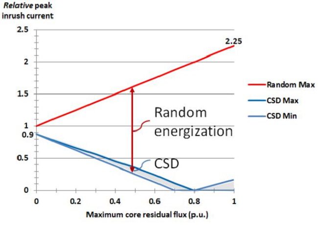
Figure5: Transformer energization relative to inrush current vs maximum core residual flux


Hello Sir, we have a similar situation to mitigate for interconnection to the grid of a PV solar farm in NC.
Can we discuss more details please.
Hi
Please connect me on LinkedIn.