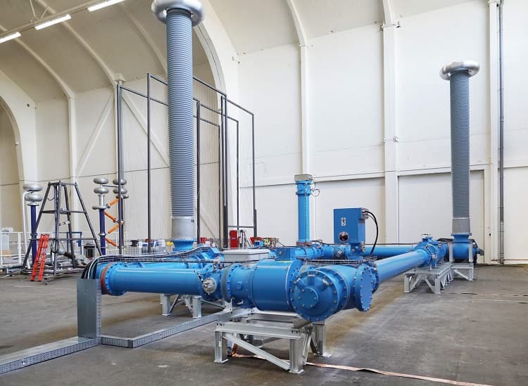
Photo from PROMOTioN website about installing test equipment for 320kv HVDC GIS test equipment in the DNV GL’s KEMA by ABB.
We have already explained about HVDC disconnectors on the Switchgear content website.
You can find more information about HVDC disconnector switches here and Filter Earthing Switch(FES) Role In HVDC Grids here.
HVDC disconnector switches:
HVDC disconnecting switches (DS) are used to disconnect various circuits in HVDC transmission networks. For example, the HVDC DS is applied to switching duties such as line or cable-charging current switching, no-load line, or cable transfer switching, in addition to disconnecting equipment including a converter bank (thyristor valve), a filter bank, and a grounding line. HVDC DS is also applied to DC switchgear to terminate the residual or leakage current through an interrupter after clearing a fault current.
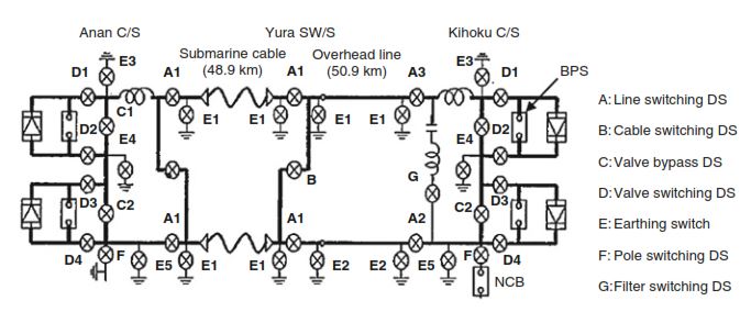
Figure 1: Example of a single-pole diagram of HVDC disconnecting switch in bipolar HVDC system
Figure 1 shows an example of a single-pole diagram with related switching equipment (except for the Metallic return transfer breaker) in the bipolar HVDC transmission system in Japan. In general, the requirements for HVDC DS and ES in the HVDC system are similar to the HVAC DS and ES used in the AC system, but some equipment includes additional requirements depending on their application. Table 1 gives major switching duties imposed on these HVDC DS (CIGRE JWG A3/B4.34 2017).
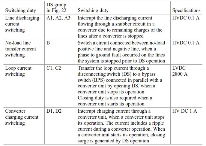
Table 1: Main switching duties of disconnecting switch (DS) applied to the bipolar HVDC system
HVDC disconnector switch groups:
Group A: The DS is required to interrupt the line discharging current due to residual charges of a submarine cable which has a relatively large capacitance (approximately 20 μF). The residual voltage induced in the line after a converter halt is discharged through a snubber circuit in a converter bank at both C/Ss (Anan C/S and Kihoku C/S) to the ground. The discharge time constant is about 40 s, which corresponds to a discharging time of 3 min. The discharge current was set to 0.1 A based on the value calculated from the residual voltage of 125 kV and the resistance of the snubber circuit in the thyristor valve.
Group B: The DS is normally used to switch a faulted transmission line to a healthy neutral line in order to use the neutral line for a transmission line temporarily or permanently after the system is completely stopped. This requires the same specifications as the group A DS.
Group C: The DS is required to transfer the nominal load current from the DS to the bypass switch (BPS) connected in parallel with a converter bank in order to restart the bank unit. The specification of the transfer current is 2800 A in this project. Figure 2 illustrates a nominal current transfer process from the DS to the BPS.
At the first, the upper converter bank unit is stopped and the lower converter bank unit is operated. In order to operate the upper bank unit from a halted condition, the DS C1 is opened next to commutate the nominal current into the BPS. Based on the analysis with an equivalent circuit of the current transfer process shown in Fig. 2 c, the requirements for the group C DS are given by the voltage of DC 1 V at a nominal current of 2800 A, where the voltage was calculated with the resistance and inductance per unit length corresponding to the current transfer length including DC-GIS.
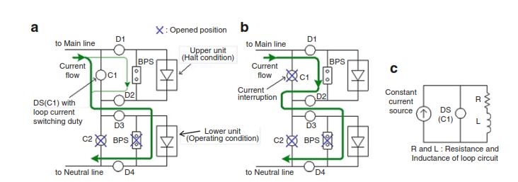
Figure 2: Current transfer DS operation of group C. (a) DS close position, (b) DS open position, (c) equivalent circuit of DS
Group D: The DS is required to interrupt a converter bank charging current when a converter bank unit is stopped. Even if the thyristor valve is halted, a ripple current flows through the stray capacitance of the converter bank. The analytical result shows that it is highly probable that the ripple current is chopped less than 1 A, and the recovery voltage due to the difference between the residual DC voltage of the converter side and the DC voltage of the line side which includes ripple components is less than 70 kV as shown in Fig 3.
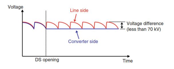
Figure 3: Voltage difference between DS contacts
Conclusion about HVDC disconnector switch grouping:
The switching performance of all HVDC DSs of groups A to D was designed based on the AC DS, and its performance was confirmed by factory tests with the testing conditions shown in Table 1 There are no significant design differences between HVAC DS and HVDC DS except for the creepage distance, which is about 20% longer for HVDC applications.
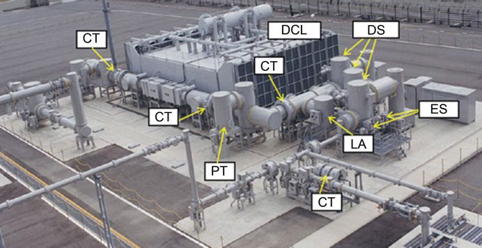
Figure 4: DC-DS&ES, DC-CT&VT, DC-MOSA (LA) used for 500 kV-DC GIS
Gas-insulated switchgear (DC-GIS) composed of several HVDC DS and earthing switches (ES) is also applied in HVDC networks close to a coastline. Figure 4 shows an example of DC-GIS including DC DS and DC ES that were installed at the converter station in the bipolar HVDC system, which was commissioned in 2000.
Figure 5 shows an air-insulated HVDC-DS with loop current switching (group c) shown in Table 1 installed by GE company install in INDIA.
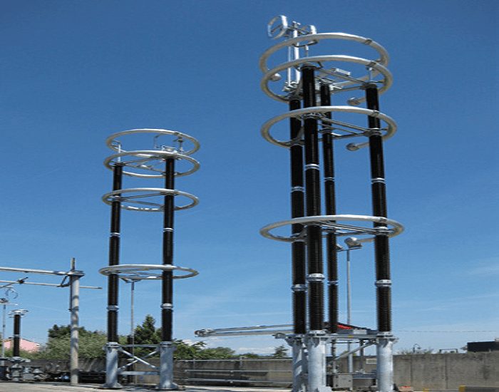
Figure 5: 800 Kv HVDC disconnector switch knee type design by GE in India


