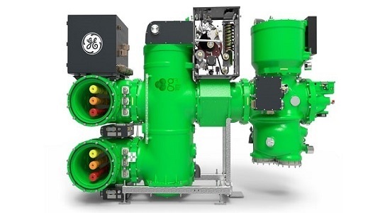
Photo from GE Vernova company SF6 free GIS product
In this article speak about brief overview of indicators for end-of-life of gas insulated switchgear, and what has to be done when end-of-life is reached. Furthermore, options for life extension of GIS with non SF6 gases and gas mixtures are discussed
Some parts of the GIS equipment are subject to ageing and deterioration mechanisms.
These ageing processes should be considered when determining future performance and residual life of the equipment and should be targeted by condition monitoring programmes.
This section considers the following:
• Critical technical performance factors.
• How these factors might affect residual life.
• Diagnostic techniques that can help determine residual life.
There are two different indicators for end-of-life:
1- The specified end-of-life of the GIS is reached:
End-of-life of GIS is either specified by the end user, reflecting the intended time until replacement of the equipment should be done, or the end-of-life of GIS is specified by the equipment manufacturer stating a minimum lifetime (which can be extended), or by an increased failure rate indicating end-of life.
2-End-of-life of the insulation gas mixture is reached:
Non-SF6 gases or gas mixtures may age during lifetime e.g. due to decomposition and reach an end-of-life stage. Here, a first indicator for end-of-life would be the gas lifetime statement of the equipment manufacturer.
Exemplary life limiting factors in GIS equipments are listed as below:
1-Mechanical wear of circuit breakers:
The designed mechanical lifetime is usually defined by the permitted number of off-load switching operations. It is limited by mechanical wear and/or fatigue life of highly stressed parts The highest stressed parts of the circuit breaker are the energy storage system and the mechanical chain between the energy storage element and the moving contacts. If applicable, the impact of non-SF6 gases or gas mixtures on mechanical wear of different circuit breaker designs (e.g. CO2-breaker, vacuum breaker) has to be discussed between the end user and the equipment manufacturer.
The following diagnostic techniques may be helpful in assessing residual life:
- Charging time
- Contact timing
- Static contact resistance
- Travel records
- Trip coil current
- Vibration analysis
2-Electrical wear of circuit breakers:
The contact system has a limited capability to interrupt fault currents because of contact erosion and nozzle ablation.
The wear of contacts caused by the arc during circuit-breaker switching operations may be estimated by calculation. The physics of arc-induced contact wear is complex, but simplified expressions have been derived that allow contact wear to be calculated with acceptable accuracy. The most commonly used methods assume the mass of contact material lost during each operation to be proportional to the time integral of the arc current squared.
One of test method for measuring waer of circuit breakers is Dynamic (Contact) Resistance Measurements (DRM).
In photo1 you can see DRM test curves: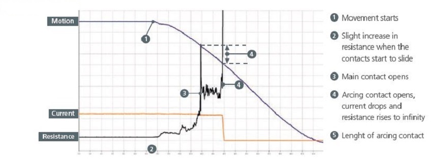 Photo1: Dynamic (Contact) Resistance Measurements (DRM) curves in circuit breaker
If applicable, the impact of non-SF6 gases or gas mixtures on electrical wear of different circuit breaker design (e.g. CO2-breaker, vacuum breaker) has to be discussed between the end user and the equipment manufacturer. If degradation of gases or gas mixtures during switching is to be expected, the impact on lifetime of circuit breaker should be discussed as well.
3-Deterioration of grading capacitors of circuit breakers:
Grading capacitors used in multi-break circuit breakers have been found to exhibit a number of deterioration mechanisms, and in some cases mechanical
or electrical failure has occurred.
It has to be discussed between the end user and the equipment manufacturers if deterioration of grading capacitors is a special issue for circuit breaker designs with non-SF6 gases and gas mixtures.
Some deterioration mechanisms effecting GIS grading capacitors can be detected using partial discharge techniques as described later. Other defects may only be detected by visual inspection.
4-High-speed earthing switches: For HV GIS, high speed earthing switches have the duty to make rated short circuit currents for at least two times, and to switch rather small induced currents. Thus, they are usually unlikely to be the life limiting factors of HV GIS with SF6.
If application of non-SF6 gases and gas mixtures requires different high-speed earthing switch design the impact on mechanical or electrical wear should be discussed between the end user and the equipment manufacturer.
Besides visual inspection, resistance test, timing tests and travel curve measurement may
be useful for assessment of the device.
In photo2 we can see high speed earthing switch in GIS:
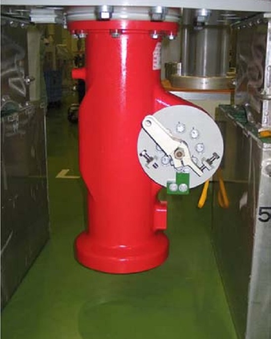
Photo2: High speed earthing switch
5-Disconnectors and (maintenance) earthing switches:
Disconnector and earthing switches mostly have no or small current making or breaking capacity, and therefore have mainly a mechanical lifetime. Some disconnector/earthing switches are fitted with arcing contacts and can make or break bus transfer currents, bus charging currents or induced currents of transmission lines (earthing switches). For these switching duties, electrical wear of arcing contacts can occur.
If additional gas ageing effects due to switching have to be considered, the impact on lifetime should be discussed between the end users and the equipment manufacturer.
As in the case of circuit-breakers, an initial idea of mechanical wear of disconnectors and
earthing switches can be obtained from the operations counter and knowledge of the mechanical endurance class of a device, while more specific indications may be obtained using diagnostic techniques. Most frequently, the motor running times for ‘open’ and ‘close’ operations are measured. In some cases, the motor current and the contact resistance are measured as well.
6-Current carrying components including contacts:
In SF6 GIS, as well as in non-SF6 GIS, if mechanical integrity is maintained,there is no ageing mechanism affecting current carrying contacts.
The current carrying ability of the primary circuit can be tested by resistance measurement. Since the resistance to be measured is of the order of micro Ohms, the measurement is typically performed by passing a current of 100 A DC or higher through the primary circuit and measuring the resulting voltage differences. The four wire method is used to prevent the current supply leads and voltage probes from influencing the measurement. Commercial micro Ohm meters that work on this principle are available.
The values obtained may be compared to those originally obtained during tests after installation on site.
For GIS with SF6 gas: SF6 gas begins to decompose at high temperatures and the techniques described below for monitoring decomposition products may reveal the presence of a hot contact within a gas compartment. Additionally, once arcing and particulate debris are present, the PD techniques described below may be able to detect and locate a deteriorating contact.
7-Gas quality :
A first indicator for end-of-life of non-SF6 gases and gas mixtures would be the gas lifetime statement of the equipment manufacturer. A gas quality check (if possible) might indicate that the equipment can be used longer, or that the gas has to be replaced if its end-of-life condition is reached. As for SF6, this will require a replacement of the desiccants.
For GIS with SF6 gas :Gas can be tested for decomposition products on-site using chemical reaction tubes
that change colour in the presence of certain reactive gases. Tubes sensitive to SO2 and to HF are available. However, since HF reacts rapidly with metals to form metal fluorides, the use of tubes sensitive to HF is not recommended. The tubes sensitive to SO2 are also sensitive to SOF2.
A gas sample may also be sent off-site for laboratory analysis by gas chromatography or infra red spectrography. Stainless steel cylinders with a volume of less than 1litre are recommended for this purpose. This method provides a more accurate analysis but is more expensive and the results are not immediately available.
In photo3 we can see an example SF6 gas purity and analyzer device:
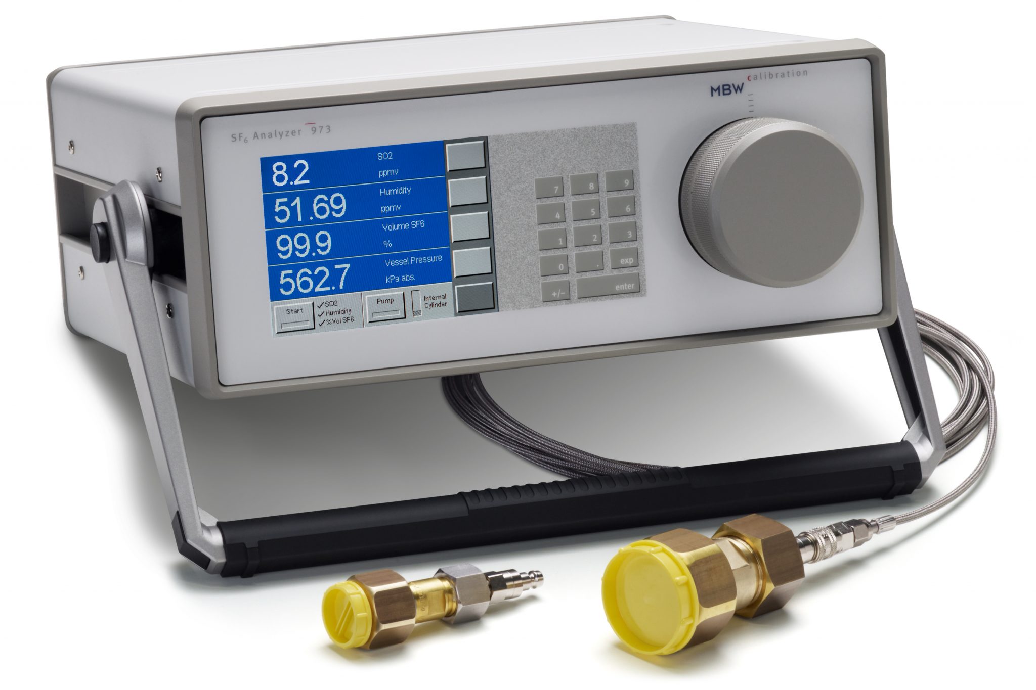
Photo3: SF6 gas purity and analyzer device
8- Particulate contamination of gas:
The insulating performance of a gas or gas mixture and of insulator surfaces may be compromised if field-enhancing defects, such as particles, are present.
Particles may be generated by the wear of moving parts, such as conductor sliding contacts and the contacts of switching devices. If particles can also be generated by other ways, e.g. decomposition of non-SF6 gases or gas
mixtures, their impact on the insulation performance of GIS should be discussed between the end user and the GIS manufacturer.
For GIS with SF6 gas: Defects such as small conducting particles generate partial discharges, which are
accompanied by electromagnetic transients and acoustic vibrations. Both of these have
formed the basis of sensitive methods that have been developed for detection, recognition
and location of defects.
Hampton and Meats developed a diagnostic technique that makes use of the electromagnetic radiation in the UHF band generated by discharging defects. UHF signals may be detected with comparatively simple, purpose built coupling devices installed within the GIS. Where no such provision has been made it is sometimes possible
to detect signals using external sensors that can be applied at breaks in the conducting enclosure, such as contact viewing windows, through which electromagnetic radiation can pass.
9-Gas leakage:
Possible origins and causes of gas leakage in GIS include pipework connections, corrosion at bolted flange enclosure joints (outdoor equipment), damaged or degraded seals or bushings (insulators), adherence of dust, particulate or other foreign material to dynamic seals, and porosity in enclosure castings or welds. These causes are rather general and mainly independent from the gas being used inside the GIS.
For GIS with SF6 gas : Where a loss of gas from a compartment is identified, external checks with leak detection methods may allow the source of the leak to be determined. by the methods applicable to locating leaks in service, negative ion capture detectors and electron capture detectors are stated to have sensitivities of 20 mg/a SF6 or 1 ppmv and 2 mg/a SF6 or 100 ppbv, respectively.
In photo 4 we can see Electron Capture Detector(ECD) Method For Sf6 Gas

Photo 4: Electron Capture Detector
Gas leakages may become an important life limiting factor if the required leakage rates can not be achieved. In the future the leakage rates may be defined by environmental regulations.
In photo 5 we can see a SF6 gas detector device:
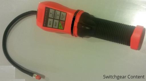
Photo 5: SF6 gas leakage detector equipment
10-Filters:
Depending on the installed amount and filter type, filters themselves are usually not life-limiting, but they are relevant for maintenance (to be replaced after opening of compartments). Filters generally adsorb both humidity and decomposition products and should be specified with respect to the type and amount of filter material needed for each gas or gas mixture.
For GIS with SF6 gas:
An indication that the molecular sieve is becoming exhausted may be given by the gas
quality measurements.
Filters themselves are not a life limiting factor rather they are a maintenance issue.
11-Solid insulating parts (GIS internal parts):
With state-of-the-art manufacturing technology and quality control (no voids or metallic inclusions), solid insulating parts are usually not subject to any ageing.
If any contamination from the gas can be excluded, solid insulating parts may not be life-limiting components of the GIS.
For GIS with sf6 gas:
The guide takes only GIS internal insulation into consideration. It does not apply to SF6-Air and SF6-Oil bushings as the life limiting factor may well be on the non SF6-side.
In their work on the long term performance of SF6 insulated systems, Task Force observed that partial discharge measurement may be able to detect voids in solid insulation, provided sufficient sensitivity can be achieved and pulsed discharge activity occurs. The sensitivity that can be normally achieved in on-site tests with UHF technique will allow critical voids to be detected.
Evolution of PD intensity can be used as an indicator of ageing of epoxy impregnated paper insulated air bushings or epoxy resin filled voltage transformers. If the observed level of PD increases it is a sign that critical ageing is occurring.
12-Metallic enclosures:
Deterioration of flanges due to moisture ingress can be seen as a critical ageing mechanism, which is independent of the gas or gas mixture inside the GIS. Hence, metallic enclosures may be life-limiting components.
For GIS with sf6 gas:
Signs of corrosion and moisture ingress at the enclosure flanges, particularly for outdoor compartments, can be obtained by visual inspection. The condition of any protective coating may similarly be checked. SF6 leakage may be an indication of flange corrosion.
13- Gas seals:
The material used for the sealing function must be able to provide sufficient gas tightness over the lifetime under application conditions. Main factors causing ageing are the material used, temperature, UV radiation, exposure to oxygen and their combination. If only materials are applied which are qualified for every gas or gas mixture, seals may not be life-limiting components.
For GIS with SF6 gas:
The performance of gas seals can be monitored by SF6 leakage detection methods.
When any work requiring internal access to the GIS is performed, the opportunity should be taken to establish the condition of the seals. The seals may be examined or analysed and residual life estimations made. An investigation into the deterioration of O-rings sampled from GIS and gas circuit-breakers aged 20 to 30 years has been reported.
In the investigation, compression set cs, as defined in the following equation, was used as an indicator of degradation.
14-Pressure relief device:
Two main ageing mechanisms of pressure relief devices are corrosion (e.g. due to attack by moisture) and/or fatigue (e.g. due to temperature cycles).
Both mechanisms are rather independent from the gas inside GIS.
There is no non-destructive method suitable to monitor / check the actual state of the pressure relief devices in service. The visual inspection is useful, but it can check the visible traces of the corrosion only. However monitoring gas leakage can identify corrosion that is not visible. In case of any deterioration observed repair shall be considered as soon as possible.
The ageing caused by fatigue can cause the decrease of the operating pressure of the bursting disc. In case of any unintentional operation the rupture discs of the affected GIS shall be tested. Several pieces shall be delivered to the laboratory of the manufacturer and checked very thoroughly. If necessary all rupture discs shall be exchanged (this procedure can be applied in other cases as well, if there is any suspicion of ageing).
The condition of the bursting disks will generally not be a life limiting factor. However it will certainly be taken into account when considering whether to refurbish or replace the GIS.
If refurbishment of a GIS compartment is being undertaken for other reasons, it is recommended that bursting disks of the graphite type will be replaced to ensure that target life extension is achieved.


