High voltage disconnect switch introduction:
A high voltage disconnect switch and earthing switch is a mechanical switching device that earths parts of an electrical circuit.
high voltage disconnect switches are primarily used to visualize whether a connection is open or closed. Different from circuit breakers, disconnectors do not have the current interrupting capability.
Therefore, an AIS high voltage disconnect switch cannot be opened when it is conducting a current and when a recovery voltage builds up across the contacts after opening. A disconnecting switch can interrupt a small current when, after opening, a nominal voltage appears over the contacts.
Earthing switch is predominantly used to make parts of the circuit including equipment safe to access by bringing them to earth potential. Earthing switch may be associated with a disconnecting switch or be independent of a high voltage disconnect switch.
Overview in capacitive and no load transformer switching:
We have already explained about the capacitive current switching test for high voltage disconnect switches here.
High voltage disconnect switches are not intended or rated to interrupt current, but, by virtue of the fact that they are operated under live conditions, they are expected to be capable of interrupting small currents.
The following note is added to the IEC definition of disconnecting switch:
A disconnecting switch (disconnector) is capable of opening and closing a circuit where the either negligible current is broken or made, or when no change in the voltage across the terminals of each of the poles of the disconnecting switch occurs.
Although not specifically stated, this statement can be interpreted as referring to small capacitive charging currents and to loop switching, also known as parallel switching and, in a specific application, as bus-transfer switching.
IEC 62271-102 confirms this and sets an upper limit of 0.5 A with respect to “negligible” capacitive charging current with higher values subject to agreement between the user and the manufacturer (IEC 62271-102 Rated
bus-transfer currents are also addressed in the standard as follows:
52 kV < Ur < 245 kV, 80% of the rated normal current of the disconnecting switch but limited to 1600 A; 245 kV Ur 550 kV, 60% of the rated normal current of the disconnecting switch; and Ur > 550 kV, 80% of rated normal
the current of the disconnect switch but limited to 4000 A.
In practice, particularly in North America, air-break disconnecting switches are commonly used to switch out unloaded transformers.
A further common practice is to extend bus transfer to switching between parallel transmission loops, albeit at lower currents due to the higher loop impedances.
Another practice used extensively in North America and to a limited degree elsewhere is to add auxiliary interrupting devices to reduce the severity of the switching event, e.g., minimize the occurrence of restriking, or achieve higher interrupting capability.
Unloaded Transformer Switching by AIS high voltage disconnect switches:
AIS high voltage disconnect switches are used for the high-side switching of unloaded transformers in the range of 72.5–245 kV where the magnetizing current is usually 1 A or less. The transformer can be represented as a series RLC circuit as shown in Fig. 1, and the associated oscillation is underdamped with an amplitude factor of 1.4 per unit or less.

Fig 1: Unloaded transformer switching: transformer equivalent RLC circuit
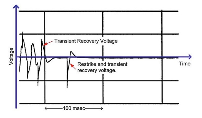
A trace from an actual field-switching event is shown in Fig. 2.

Fig 2: Field trace showing transformer-side oscillation after current interruption
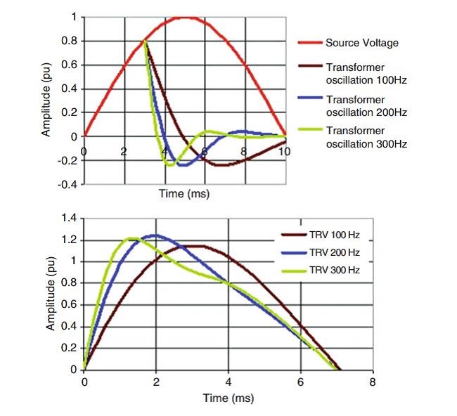
The transient recovery voltage (TRV) across the disconnecting switch is thus the difference between the source voltage and the transformer-side oscillation as illustrated in Fig. 3.

Fig 3: Unloaded transformer switching (Transient recovery voltage is the difference between the
source- and load-side voltages)
A current interruption is essentially a dielectric event occurring when the contact gap is sufficient to withstand the TRV.
Breaking the magnetizing current of unloaded transformers is a repetitive break-make event with numerous restrikes. Restriking may result in an inrush current, which prolongs the arcing time by its duration and wear on the arcing horns.


