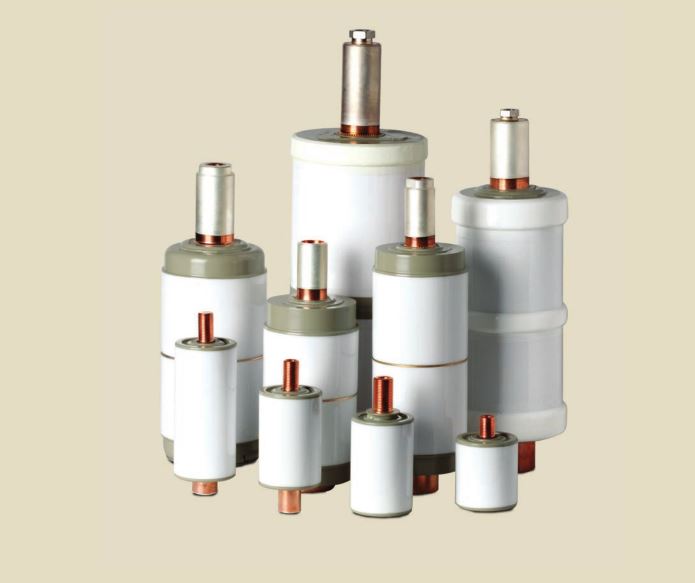
Photo from VITZROTECH company vacuum interrupter catalog (just for display)
About vacuum condition monitoring in vacuum interrupters:
Vacuum interrupters (VI’s) are the primary circuit interruption medium for medium voltage power systems and increasingly are also used in low and medium and high-voltage systems. The VI performance requires that the pressure inside the VI be maintained below 10 hPa (1 hPa = 100 Pa = 0.75 torrs).
Vacuum interrupters are tested to have an internal pressure ≤10 -3 hPa before leaving the factory.
The performance of the vacuum interrupter is connected to the vacuum level, however, its performance is not simply proportional to the pressure. Instead, the pressure inside the VI is best considered by putting the pressure into three groups.
The pressure can be grouped by low pressure with p< 10 -6 hPa, mid-range pressure from p~10 -3 hPa to the Paschen minimum pressure, and finally a high pressure. High pressures generally only occur if the VI will ultimately go up to the air.
In the low-pressure range, the Vacuum Interrupter will continue to function. In the mid-range, the dielectric and interruption performance will be degraded, as also in the up-to-air range.
one point to note with the dielectric performance is that it is lowest in the mid-range pressure and actually improves in the up-to-air range, although it is still below the level when the pressure is in the low range.
It is important to realize that none of the techniques discussed here cover the full range of pressure inside a vacuum interrupter from low pressure to up-to-air. Each covers a certain range, and this is highlighted in the text and in Table 1. The results of certain methods are also a function of the design of the vacuum interrupters.
Additionally, the output of some methods can be affected by the composition and pressure of the surrounding gas that could potentially leak into the Vacuum Interrupter. The two main situations are air at atmospheric pressure, and 1.0-1.5 bar absolute pressure of SF6 gas (generally used in GIS switchgear). The following discussion focuses on VI’s in air. Table 1 summarizes the general application in SF6 environments, and the discussion for each method goes into more detail, including practical issues of using the method with GIS switchgear. Table 1 also summarizes the output of the test methods The extensive use of vacuum interrupters in medium voltage switchgear is raising the issue of how to confirm the vacuum integrity in the field, particularly after multiple decades in service.
Inspection of vacuum interrupter’s after more than 20 years of field use has shown mixed results. It must be noted, however, that the VI’s are only one part of a system; the rest of the system including the mechanism, control circuitry, circuit design, etc., must also function in order for the vacuum interrupter’s to fulfill their role.
You can find more information about the Vacuum interrupter testing method here.

Table 1: Comparison of vacuum level measurement methods, including the vacuum level that can be measured, whether the measurement is affected by the design of the VI, the type of output, and compatibility with SF6
Vacuum Interrupter Condition measurement by mechanical pressure monitoring method description:
Atmospheric pressure produces a significant closing force on the moving terminal of the Vacuum Interrupters. For Vacuum interrupter’s used in circuit breakers, this force is typically on the order of a few hundred newtons. When the vacuum is completely lost, the external atmospheric pressure is balanced by the same pressure inside the VI, and the closing force is significantly reduced, leading to a change in the mechanical behavior of the Vacuum Interrupter. Diagnostic methods looking for this change can only detect when the VI is completely up-to air.
For example, even the very “high” pressure at the Paschen minimum is more than sufficient to maintain the full closing force on the Vacuum Interrupter.
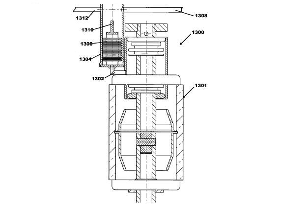
The main method for mechanical pressure monitoring attaches an additional moving part to the Vacuum Interrupter using a bellows or similar (Figure1), and the complete loss of vacuum then results in the motion of this component. This additional part is free to move, unlike the moving contact which is constrained in its motion by the circuit breaker mechanism. A detection system then observes the different positions of the additional moving part and reacts accordingly. Depending on the detection system, this setup can continuously monitor the Vacuum Interrupter(VI). The motion of the additional moving part is dictated by the design of the additional part and not of the overall VI, therefore it is independent of the particular VI design. The method could be applied to low, medium, and high voltage VI’s.
It is theoretically possible to use the closing force on the moving terminal of the VI to observe the loss of vacuum. Atmospheric pressure normally applies a force on the order of a few hundreds of Newtons to the VI moving terminal. For comparison, the circuit breaker applies a closing force of typically a few thousand Newtons. Therefore, the loss of closing force on the VI can be difficult to determine from the mechanical behavior of the breaker, because of the small size of the VI closing force as compared to the circuit breaker closing force. For vacuum contactors, the lower force from the contactor mechanism might allow a diagnosis of complete vacuum loss from the mechanical behavior.

Figure1: Pressure monitoring via additional bellows (1306) attached to the VI (1301). a tube connects the additional bellows to the VI (1302), and the movement of the part (1310) during the loss of vacuum breaks the light path between (1308) and (1312) [ source: US7302854]
Vacuum Interrupter monitoring by mechanical pressure monitoring method background:
The technique measures a mechanical change due to the loss of the closing force from the atmospheric pressure on the moving terminal of the Vacuum Interrupter(VI). This technique would only provide a pass/fail measurement of whether the Vacuum Interrupter(VI) was up-to-air or not. The pressures around the Paschen minimum and other points where the VI performance starts to be affected are far too low to produce any detectable mechanical change.
A key part of the measurement method is the detection system. One implementation uses an optical system to detect the motion. The motion disturbs an optical path between two fibers, either stopping the light transmission or allowing the light through by inserting a mirror or removing a block. The light can be guided through fiber optics to the detection system. This maintains an electrical separation between the Vacuum Interrupter(VI) and the measurement system and allows the electronics to be placed in the low voltage compartment of the switchgear. A second implementation uses the motion of the additional part to make or break an electrical connection. Since this contact must be electrically isolated from earth, this signal must be converted into an optical signal for transmission along with a fiber optic, or be converted into a wireless signal (RF, etc.). This requires a microelectronic circuit near the Vacuum Interrupter to convert the signal, together with some method of powering the circuit while maintaining the electrical isolation.
Mechanical pressure monitoring has been implemented into prototype products from one manufacturer. The field experience with this method is not known.
Vacuum Interrupter mechanical pressure monitoring method advantage and disadvantage:
The moving part needed for the pressure monitoring must be installed on the Vacuum Interrupter (VI) during its initial manufacturing. There is no possibility to add this to already built VI’s. It is conceivable to add VI’s with this feature to existing circuit breakers, along with the monitoring equipment. However, the practical issues with fitting a Vacuum Interrupter(VI) with the extension for the extra part into existing equipment will most likely prevent this. The method is generally compatible with SF6, oil, and solid insulation as long as practical issues of space, guiding the light to the detection equipment, etc., can be dealt with.
The main risk is the reliability of the measurement equipment as compared to the VI’s. In general, the additional parts brazed to the VI lead to additional potential leak paths. Also, these components can be more fragile and/or vulnerable to damage during installation that can lead to a loss of vacuum. The optical technique has the advantage of moving the non-optical components into the low voltage compartment of the switchgear. However, fiber optics are vulnerable to misalignment of the two fibers, damage on installation, blockage by condensation or dust, etc. The electrical contact method of motion detection needs a powered microcircuit near the VI that is also electrically isolated. This creates several potential failure modes related to the microcircuit reliability, successful transmission of the signal, powering of the circuit, and maintaining the electrical isolation.


