Photo from EE power website
General about Zero flux CT:
Increased complexity in the power grid, such as the introduction of power electronic based devices, calls for traceable measurement techniques to accurately determine high frequency components of high electrical currents. For non-intrusive measurement of electrical AC and DC currents magnetic coupling in current transformers are widely utilized.
The fact that the error of a current transformer is directly linked to the magnetization of the core, naturally leads to consideration of methods to reduce this flux. Such a method is known as the zero-flux technique where a balancing compensating current creates zero-flux in the magnetic core.
Zero flux current transformers is kind of Low-Power Instrument Transformers (LPIT).
Low-Power Instrument Transformers offer advantages in terms of size, power consumption, safety,accuracy and signal reliability. With the introduction of digital communication in substations according to the IEC61850-9-2 standard, the use of LPITs in GIS will become more widespread.
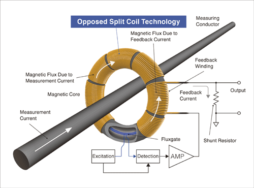
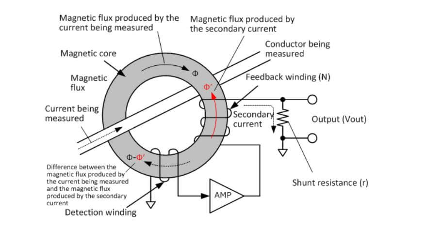
Zero flux current transformers are precision instruments for AC and AC/DC measurements.(they used now most for HVDC GIS). The measurement principle of an AC zero flux current transformer is shown in Figure 1.

Figure 1: principle of an AC zero flux current transformer
A detection winding senses the magnetic flux in the core. A closed control loop with an amplifier and a feedback winding generates a secondary current which cancels the flux generated by the primary current, thus “Zero flux CT”. The secondary current flows through a precision burden resistor generating a voltage signal proportional to the primary current. The magnetic material of the core is not excited and does not show hysteresis or saturation.
At DC or low frequencies, the flux does not cancel as the detection winding is unable to measure the residual flux. For DC measurements, a DC flux sensor is added – either a Hall probe embedded in the core or a flux gate circuit with two more control and sensing windings.
Zero flux current transformers advantages : AC zero flux sensors have a high linearity and precision and are not affected by the magnetic core’s characteristics. The phase error is small, and the accuracy is determined mainly by the precision burden resistor. An additional Hall probe or flux gate detector enables DC measurements. The sensor is robust regarding electromagnetic interference.
Zero flux current transformers disadvantages: The sensor needs a power supply and an amplifier. A defective secondary circuit can produce hazardous voltages.
Example of use Zero flux current transformers in Kii-Channel project HVDC link for outdoor 500 kV DC GIS:
The CTs used in the Kii-Channel project are zero-flux CTs.
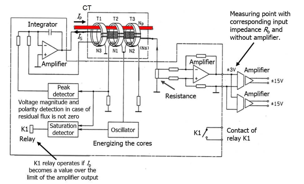
Figure 2 show the block diagram and the hardware of the CT. The current to be measured Ip generates a magnetic flux affected by the current ls in the secondary winding (Ns).
The flux is sensed by three toroidal cores located within the GIS compartment. Cores N1 and N2 are used to sense the DC components of the remaining flux. N3 gives the AC component. An oscillator drives the pair of DC flux-sensing cores (N1 and N2) into saturation in opposite directions. The resulting current peaks are equal in both directions if the remaining DC flux is zero. If not zero, their difference is proportional to the residual DC flux. Adding the AC component by N3, a control loop is set up to generate the secondary current that makes the flux zero. A power amplifier provides the current Is to the secondary winding Ns. The secondary current is fed to the burden resistor to convert the current into an equivalent voltage signal. The burden resistor and the stability of the differential amplifier determines the measurement precision.

Figure 2: block diagram and the hardware of the HVDC zero flux current transformer


