Substation Automation system (SAS) is a system to enable an electric utility to remotely monitor, control and coordinate the distribution components installed in the substation. High speed microprocessor based Remote Terminals Units (RTUs) or Intelligent Electronic Devices (IEDs) are used for substation automation and protection. These IEDs are installed in strategic locations for collection of system data and automatic protection of substation equipment’s. Data communication between the control center and IEDs in remote locations and among the IEDs becomes an important issue to realize the substation automation functions. Various protocols are used for tele-control purpose, but none of them fully support the interoperability among IEDs supplied by different vendors in the substation. These protocols are Modbus, Modbus Plus, DNP 3.0, and IEC 60870.
The main substation automation system (SAS) function consists of several sub-functions which are appropriately interfaced. These sub-functions are known as Logical Nodes (LN).
A logical node is realized through an object class, called logical node class. For example, XCBR is a logical node class for monitoring and operation of circuit breaker. A logical node class consists of a set of data belonging to different class. For example data “Pos” of data class type “DPC” is a member of logical node class “XCBR”. Further each data class inside a logical node class consists of a set of data attributes. For example, data class “DPC” consists of data attributes given by Control value “ctlVal”, Operating time “operTime”, etc.
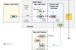
In figure 1 we can see a diagram of high voltage circuit breaker control and interlock logical nodes and logical device in process, bay and station level:

Figure 1: High voltage circuit breaker control and interlock logical nodes
Control parameters and logical nodes according to IEC 61850-7-4 in switchgears are:
- XCBR/XSWI/CSWI.Loc shows the control behaviour of the logical node.
- MltLev Shows if more than one source of control commands is accepted at a certain level at the same time.
- LocSta Shows the switching authority at station level.
Due to practical and technical considerations, these control levels usually do not have the same control autonomy. At bay level (local control rooms), each particular bay controller is able to take care of one or perhaps a pair of HV bays/feeders, while from the HMI located in the main control house, an operator may choose any primary or secondary switchgear to connect or disconnect power circuits. The control capability from the remote master unit is often restricted to opening and closing primary circuit breakers.
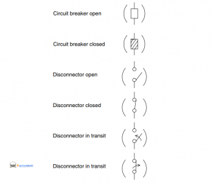
From operational point of view, as well as the common open and closed status that can be exhibited by both apparatus, the disconnector also presents as a third status that referred to in the transit condition exhibited during the operation process.
Symbols, Colors and Appearance Representing Primary Switchgear:
An efficient visual display on bay controllers and the HMI color monitor is very desirable. This calls for close cooperation between contracting departments at the SAS engineering stage. Although the style for displaying bays and feeders on the screen of the bay controller is often standardized by each IED vendor, a lot of detail may require early agreement between substation owner and SAS designer/integrator. One of these is the set of symbols used to represent primary switchgear under different conditions, so as to reduce the possibility of error in the operative procedure. Some examples of this are shown in Figure 2.

Figure 2: Switchgear different condition in substations
Switching Command Implementation:
On demand, for example by selecting a specific circuit breaker or disconnector on the monitor screen, a control dialog box appears which is used to give the “go to the control” command.
In this way, the recommended two‐step procedure, consisting of two positive and successive actions to take control, is fulfilled. For security reasons, and following the authority levels rules, adequate means must exist to verify that the person clicking has the correspondent right to execute control commands.
Another important provision to be made is that the internal coupling needs to prevent control commands being made on the same apparatus simultaneously from different control levels, such as NCC and bay level (prevention of double operation commands). The command order has to progress and be materially executed only if no constraint related to interlocking or a blocking condition exists. When there is any impediment carrying out the intended control command, a supplementary dialog box appears indicating the cause of it.
Supervision of Circuit Breaker Trip Circuit:
Perhaps the most important SAS functionality is the ability to automatically open specific circuit breakers when a fault occurs in the power system (trip order coming from protective relays). This fact means the trip circuit of circuit breakers is a critical part of the secondary system with respect to its operative availability when it is requested.
Because of that, it is common practice to implement continuous monitoring of such a trip circuit in order to detect defective contacts, weakness in power supplies or any other potential risk. This is done by forcing a current to circulate the circuit and then checking the circuit resistance. When it increases, an alarm appears. For this application, special relays on the market are recommended.
Checking Operative Constraint:
Like any other type of control system, substation control systems aim to accomplish certain constraint conditions to ensure that all changes in power system configuration are made in a safe manner for personnel, equipment and environment. Those constraint conditions are imposed on the control system by avoiding the progress of a control command when a switch operation is wrong from the operative point of view (interlocking logic) and/or through blocking signals, in cases of conditions unsafe for performing the intended switch operation (blocking condition).
Checking of Interlocking Conditions :
Several technical reasons impede autonomous switchgear operation. They include the following:
• Disconnector capabilities: These apparatus are not able to handle normal load or short‐ circuit currents when they operate.
• Earthing switch function: These apparatus are put in the closed position occasionally for inspection, maintenance or repair activities on a segment of the power circuit. They connect that segment to the earth mesh of the substation. If such a segment is energized when the earthing switch is in the closed position, severe failure will occur (short‐circuit) .
Checking of Blocking Conditions:
Switching operations require optimal condition of the respective switchgear. A circuit breaker will be explosive if an opening procedure is made slowly due to an anomaly in the operating mechanism. A disconnector may cause severe damage in instrument transformers if its opening or closing time greatly exceeds typical operation time. These undesirable scenarios bring about the necessity to avoid risking switching operation that could affect substation workers and/or involuntarily interrupt the energy flow. The security in this respect is achieved by
implementing blocking signals into the control logic in such way that the switching command (opening/closing) does not progress if any of those blocking signals are active.
Typical blocking signals include:
• SF6 gas – low pressure
• Hydraulic/pneumatic/spring – system defective
• Pole discrepancy in circuit breakers
• Motor faulty.
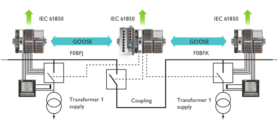
Modern power station automation systems enable the auxiliary power consumption switchgear in a power station to be integrated into the main automation system in accordance with IEC 61850. This not only eliminates the need for a separate switchgear automation system, but also saves engineering outlay.
Recently by using IEC 61850 protocol and SAS switchgear control and interlocking made a lot of progress.


