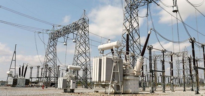
Shunt-reactor switching is by far the most common practice of the inductive-load switching. Shunt reactors are installed for overhead-line capacitance compensation, and switched in or out depending on the momentary line load. Since the shunt reactor can be treated as a lumped circuit element having a stray capacitance, the equivalent load circuit can be simplified to a straightforward LC circuit.
At interruption, actually current chopping, the LC circuit produces voltage oscillations, reaching a maximum voltage Ump, which is the 1 p.u. of the system voltage augmented with the additional current-chopping contribution. Generally, the single-frequency oscillatory TRV is of high frequency, standardized by IEC 62271-110 to values between 6.8 kHz at the rated voltage of 72.5 kV and 1.5 kHz at 800 kV.
Similar to the capacitive-current switching, the reactor current is low enough that interruption can occur after a very short arcing time. This implies that the circuit-breaker gap might have not yet reached a sufficient spacing at current zero to withstand the TRV and, if so, a breakdown is the consequence. In this case, the breakdown is termed a re-ignition because the high-frequency TRV makes it happen within a quarter of a power-frequency period after interruption.
Unlike a restrike in capacitive circuits, the energy delivered to the inductive re-ignition discharge is relatively low, being the discharge of the stray capacitance; a high-frequency re-ignition current will flow briefly and the gap may or may not recover from the event.
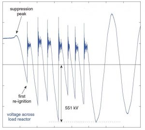
During the flow of re-ignition current, the opening gap reaches only a slightly higher breakdown voltage and the subsequent higher TRV, after re-ignition current interruption, will again lead to re-ignition.This is more likely to occur, because, during the brief conducting period, the power-frequency current in the reactor increases slightly, causing the second TRV to be steeper and potentially higher than the previous one. The sequence of re-ignitions is called multiple re-ignitions and the gradual increase in the re-ignition voltage value is called (inductive) voltage escalation.
Multiple re-ignitions may be onerous for gas and oil circuit-breakers, and this is the reason why the shunt-reactor switching is sometimes termed “a circuit-breaker’s nightmare” – also and not least because it is a daily switching operation.
 In this Fig for a SF6 circuit breaker test . Seven re-ignitions can be observed before recovery is achieved. Immediately after re-ignition, a re-ignition current of very high frequency keeps the gap conducting during approximately 100 μs. The maximum voltage reached across the load reactor is 2.3 p.u.Without re-ignitions it would have been 1.08 p.u. due to the very small chopping current. The peak value of TRV is 3.3 p.u.
In this case, despite the very small chopping current, the load voltage reached after multiple.
Multiple re-ignitions of breakers during shunt-reactor switching can be avoided by controlled switching. Using controlled, instead of random contact separation well in advance of current zero, avoids short arcing times and interruption follows when the gap has reached sufficient spacing.
References:
- Transients Due to Switching of 400 kV Shunt Reactor article by :Ivo Uglešić, Božidar Filipović,Franc Jakl,Miroslav Krepela.
- Switching in Electrical Transmission and Distribution Systems Book by René Smeets • Lou van der Sluis,Mirsad Kapetanovic • David Peelo ,Anton Janssen
- Investigation of circuit breaker switching transients for shunt reactors and shunt capacitors by: Mohd Shamir Ramli


Voltage scalation its mentioned in CIGRE report 50. What is mentioned in the last paragraph is correct but the reality is different. In operation this relay may be out of adjustment or not work properly so that translates into a problem for the operation. Normally, what techniques are used by companies in the world for the application of Reactor Switching, use of synchronized control or implement other alternatives that are mentioned in the standard as the installation of MOVs in parallel to the CB chambers
Thank you for your comment.
You can find some articles and post on the switchgear content website about controlled switching.
Which method is best suited for calculating chopping number of CB (IEEE-C37.015 or IEC 62271-110
Thank you for your comment.
In IEEE C37.015 you can find many contents about chopping numbers as Table 1 (Chopping and reignition overvoltage mitigation methods ).
Also for the range of chopping numbers for each kind of CB please see Table A1.
Annexes E, F also are useful for chopping numbers.