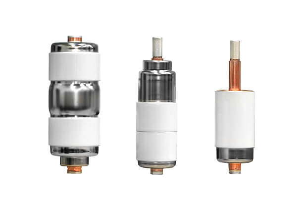
photo from Noja power company website
Introduction for vacuum interrupter & bellows:
With the advancement of technology and with the increase of global warming, vacuum circuit breakers have been considered.
Future power grids increasingly demand for better switching performance of circuit breakers, especially concerning higher speeds and lifetime operations. In medium voltage circuit breakers, vacuum interrupters (VIs) are often preferred since using a vacuum as an interrupting medium possesses superior characteristics in this application range.Vacuum interrupter is main part of vacuum circuit breaker and bellows have effective role in vacuum interrupters.
The metal bellows provides the ultra-high vacuum seal while also allowing the translational motion of the moving electrical contact in the interrupter chamber.
The mechanical lifetime of vacuum interrupter(VI) is mainly limited by the so-called vacuum bellows. In future circuit breakers, faster switching speeds will lead to higher dynamic impact-type loads. This results in the excitation of bellows oscillations with even larger amplitudes, thus reducing the bellows lifetime. Additionally, considering the increased number of switching operations in future grids, the simulation of vacuum bellows is essential for design optimization to enhance the mechanical lifetime of VIs.
Bellows role in vacuum interrupters:
A bellows made from thin stainless steel allows the contacts to open and close while retaining vacuum inside the interrupter.
The fatigue performance of the bellows limits the mechanical life of the VI. The contact opening and closing operations stress the bellows, particularly the convolutions closest to the ends. In addition to the direct motion from the operation, the bellows oscillates after the contact motion stops, further adding to the wear on the bellows.
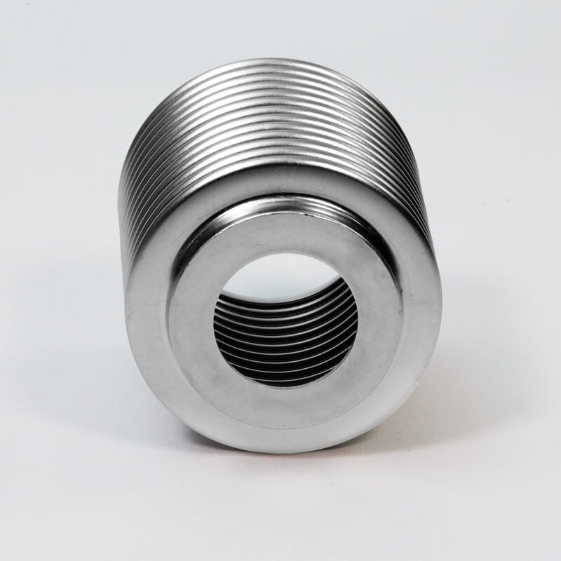
Figure 1 show a type of bellows for vacuum interrupter from Sigma-Netics company:

Fig 1: vacuum interrupter bellows made by Sigma-Netics company
The critical contact motion parameters that affect mechanical life are:
(1) steady state contact stroke or gap
(2) opening and closing speed
(3) motion damping at end of opening and closing stroke
(4) overshoot and rebound on opening
(5) mounting resilience
(6) contact bouncing on closing.
The bellows permits the motion of the moving contact while maintaining a vacuum tight seal. The bellows is made from stainless steel and usually has a thickness of about 150 µm. Three styles of bellows have been successfully applied in vacuum interrupter design:
1. Seamless: hydroformed bellows
2. Seam-welded: hydroformed bellows
3. Bellows manufactured from edge welded, thin stainless steel, washers
General and detailed information on bellows design and performance can be found in the EJMA Standards.
One end of the bellows is fixed, being brazed to the end plate of the vacuum interrupter. The other end is brazed to the moving terminal and moves with that terminal as the contacts are opened and closed. In a vacuum interrupter, the bellows is subjected to an impulsive motion as the contacts are made to open and close: the opening speed of the moving contact can go from 0ms−^1 to as much as 2ms^−1in a time of less than 100 µs.
At the end of the contact stroke, the moving end of the bellows suddenly stops. It also comes to a sudden stop when the contacts close. For some duty cycles, this open and close operation can occur many times, but in others it will occur only on rare occasions. The motion imparted to the bellows is thus anything but uniform and it is quite possible for the bellows to oscillate many times during one-open or one-close operation. For those readers interested in an analysis of this bellows motion, has developed a general analytical approach for determining the dynamic stresses that can be experienced by a bellows operating under impulsive motion.
Most vacuum interrupter manufacturers purchase their bellows from reputable bellows manufacturers and work with them to obtain the required bellows life. This is usually done by building the bellows into a practical vacuum interrupter and performing a mechanical life test on a statistically significant number of vacuum interrupter samples.
A specified mechanical life can then be assigned to the vacuum interrupter with that bellows by using the Weibull analysis. Usually the limit of a vacuum interrupter’s mechanical life is the number of operations the bellows can perform before it experiences fatigue failure. When mechanically testing a vacuum interrupter,care must be taken to stress the bellows at the operating parameters it will be exposed to in a switching device, that is, its total travel (operating gap, plus over travel) , its maximum opening speed, its maximum closing speed, and the effects of acceleration and deceleration. The reason a bellows must be tested within the vacuum interrupter is to ensure that it has experienced all the manufacturing steps that finished device it will see. For example, it should experience all the heating and cooling cycles needed to manufacture the vacuum interrupter .
These will necessarily anneal the metal that forms the bellows and thus change its granular microstructure,which will in turn affect its performance characteristics.
The mechanical life of a particular bellows not only depends on the above operating parameters, but also on its own physical parameters (i.e., the type of stainless steel), its length, diameter, thickness, the number of convolutions, and how quickly it damps its motion once the contact ceases to move. It is possible to design bellows that will perform reliably for the normal 30,000 operations required for most vacuum circuit breakers and vacuum reclosers, and in excess of 10^ 6 operations required for vacuum contactors. While vacuum interrupter manufacturers have been diligent in designing their vacuum interrupters to meet the specified mechanical life of the various switching devices, most of the vacuum interrupters never see their stated mechanical life when placed in the field.
For more information about Vacuum Interrupter(VI) Failure Reasons please see this article.
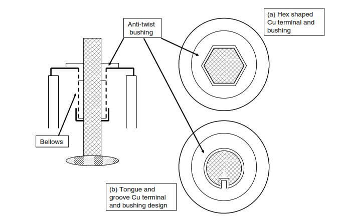
The vacuum interrupter designer has to be careful that the user cannot twist the bellows when the vacuum interrupter is placed into a mechanism. The mechanical life of a twisted bellows is severely reduced; it can be less than 1% of its design life. The torque that can be applied to the thin-walled bellows used in a vacuum interrupter before it is permanently twisted is quite low, perhaps about 8.5–11.5 Nm. In order to prevent the bellows from becoming twisted the designer must place an antitwisting bushing into it. This bushing can be locked in place by a suitable attachment to the end plate of the interrupter. The inner surface of the bushing is shaped or has a key way that prevents any rotation of the moving, Cu terminal that is attached to the bellows (see Figure 2). The bushing material can be metal or it can be a plastic material such as Nylatron. Care must be exercised when using plastic materials such as Nylatron and Valox. These materials can only be used in applications where there is a limit to the maximum permissible temperature the bushing material will experience
(i.e., the temperature at which the tensional strength will be reduced to 50% after 100,000 h). For Nylatron, this will occur at about 125◦C (it does, however, withstand a higher temperature for short periods without deformation because of its glass fiber content); for Valox DR48 the at about 140◦C. There are other higher temperature and more expensive plastics such as “Ultem 2310 R.”

Fig 2: Examples of anti twist bushings to protect the bellows from damage
The maximum permissible temperature for this material is about 180◦C and this temperature can also be exceeded for a short time (about 1 h) without serious deformation occurring.
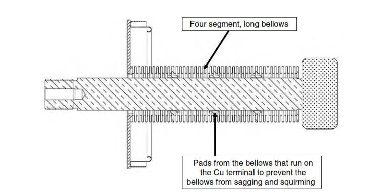
For vacuum interrupters that are used at higher circuit breaker voltages, a longer stroke is required (e.g.,at 72.5 kV a stroke of about 40 mm). To achieve this stroke the bellows must become correspondingly longer. A very long bellows will not close and open uniformly, but will squirm as it moves. When it does this the inner convolutions may well rub against the Cu terminal. This can result in considerable reduction to the bellows’ life. In order to prevent this, bellows have been developed with internal pads that ride along the Cu terminals; an example is shown in Figure 3.

Fig 3:long bellows for high voltage vacuum interrupters
Bellows & vacuum interrupters in future:
Vacuum breakers will dominate the distribution systems and in the coming years will be more compact and will have a separate electromagnetic drive for each phase.A promising development is the self-actuating vacuum interrupter: no bellows, no moving external parts, and no external operating mechanism.


