What’s the HVDC Hybrid Circuit Breaker:
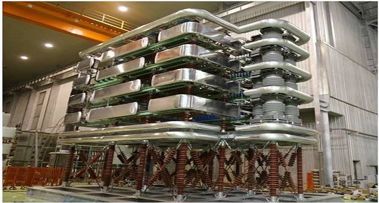
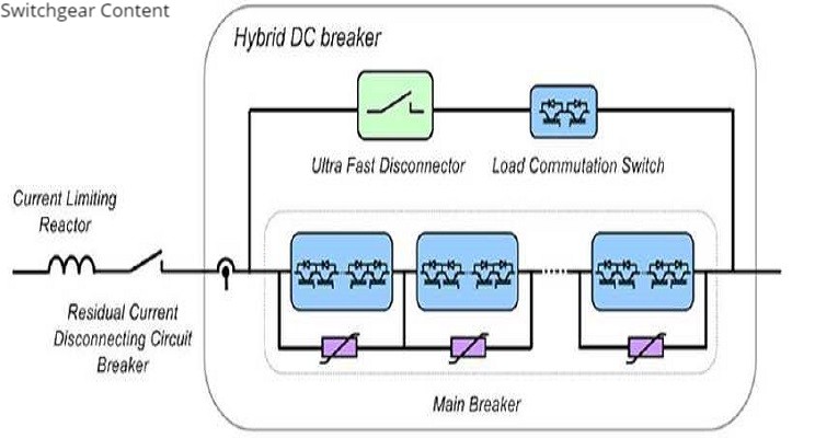
The Proactive Hybrid Circuit Breaker (PHCB) HVDC is shown in Fig1 design by ABB. This consists of two paralleled branches. The normal current path consists of a mechanical switch and a low voltage series stack of semi-conductive switches, known as the Load Commutation Switch (LCS). In parallel with these is the main current breaking element, a stack of semi-conductive switches, known as the main breaker. The energy absorption branch is combined with the secondary branch in this case to add functionality to the circuit breaker. In such an arrangement, sections of the secondary branch can be switched independently from the others. This allows the circuit breaker to act as a fault current limiter in certain situations.
During normal operation the disconnector is closed, the LCS is turned on and the main breaker is turned off. When a fault is detected, the LCS is turned off and the main breaker is turned on.The LCS provides sufficient voltage to commutate current from the primary branch into the secondary branch. The LCS may be triggered before the fault is confirmed. This would allow the detection algorithm to be processed in parallel with the circuit breaker’s operation.

Once all the current is flowing through the main breaker, the high speed mechanical disconnector is opened. When the mechanical switch is fully open, the main circuit breaker is turned off, the main breaker current is interrupted, and the line energy is dissipated in the varistors. The relatively slow series residual current disconnecting circuit breaker is used to break the leakage current through the main breaker and associated devices, which may be significant depending on how the energy absorption branch is designed. This switch also provides full isolation.
Hybrid Circuit Breaker Definitions:
The standard definitions for AC circuit breakers do not directly translate across to HVDC protection. The time frames and dynamics involved do not suit such descriptions. The topologies for DC protection are also fundamentally different and cannot be fully encompassed by the terms traditionally used in AC protection.
AC circuit breakers have a relatively long time to act compared to DC circuit breakers. Typically, the fault currents that an AC circuit breaker is interrupting will have nearly reached steady state by the time the protection acts, but this is not always the case.
HVDC circuit breakers will be required to act before the DC fault current has reached a steady state value, due to the limitations of the electronics within the circuit breakers and the converters themselves.
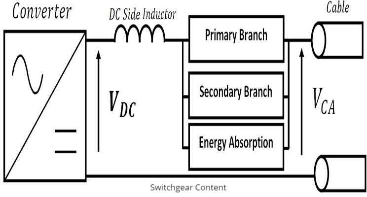
Hybrid circuit breakers contain several branches within their designs. Each branch has a specific function. The branches are typically arranged as shown in Fig 2, and are described by the terms Primary Branch, Secondary Branch, and Energy Absorption.

The main definitions HVDC Hybrid circuit breaker:
- Primary Branch: The Branch of the circuit breaker that conducts the current during normal operation.
- Secondary Branch: A Branch, or Branches, that conduct the fault current for a short period of time.
- Energy Absorption Branch: The branch which limits the voltage across the circuit breaker and absorbs any additional energy from the DC grid.
- Commutation Time: The time taken for the current in the primary branch to decay to zero, or so close to zero that the next stage in the circuit breaker’s operation can take place.
- Commutation: The movement of current between branches in a circuit breaker.
Time definitions for Hybrid circuit breaker:
- Fault Inception(T f): The moment the electrical conditions of the network at the point the protection exists change, resulting in an over current condition.
- Detection Time: The time it takes from the fault inception to the moment the protection is aware that there is a fault.
- Location Time: The time taken for the protection to decide which circuit breakers to open from the moment a fault is detected.
- Operation Time: The length of time taken for the circuit breaker to transition from the “Closed” state to the “Open State”.
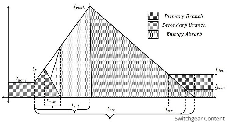
Fig 3 shows a typical fault current, with the labelled time and current ratings. This image is only meant to be illustrative. The dynamics have been exaggerated to allow the definitions to be drawn easily.

- Interruption time (T int): The time between fault inception and the circuit breaker building sufficient voltage to substantially oppose the fault current.
- Commutation Time(T com): The time taken for the current in the primary branch to decay to zero, or so close to zero that the next stage in the circuit breaker’s operation can take place.
- Clearing Time (T clr):The time taken from fault inception, to the moment that the DC line current reaches zero, or the knee current of the varistors (I knee) is reached.
- Current Limit Operation Time (T lim): The time at which the circuit breaker starts to operate as a fault current limiter.
References:
- A Novel Topology of Hybrid HVDC Circuit Breaker for VSC-HVDC Application Article by Van-Vinh Nguyen , Ho-Ik Son , Thai-Thanh Nguyen , Hak-Man Kim and Chan-Ki Kim.
- Synthetic Testing of High Voltage Direct Current Circuit Breakers A thesis submitted to The University of Manchester ,Oliver Nicholas Cwikowski.
- ABB Hvdc circuit breaker catalogue.
- Design of Test-Circuits for HVDC Circuit Breakers, R.P.P. Smeets, A. Yanushkevich,N.A. Belda, R. Scharrenberg.
- A Review on HVDC Circuit Breakers Ataollah Mokhberdoran*, Adriano Carvalho†, Helder Leite◊, Nuno Silva.


Very good overview and description of operation of hybrid HVDC circuit breaker. A more harmonized timing and breaker operation related termilogies are described in detail in CIGRE TB 683, a very comprehensive document on HVDC switchgear. I see some termilogies, e.g. interruption time in this blog conflicts with the definition in the TB brochure.
Thank you for your attention