standards:
It is assumed that a feeder is in the energized condition and the operating sequences described below are of
a general nature for GIS.In all cases applicable safety and specific operating rules shall be observed.
Sequence of operation for isolation of a feeder:
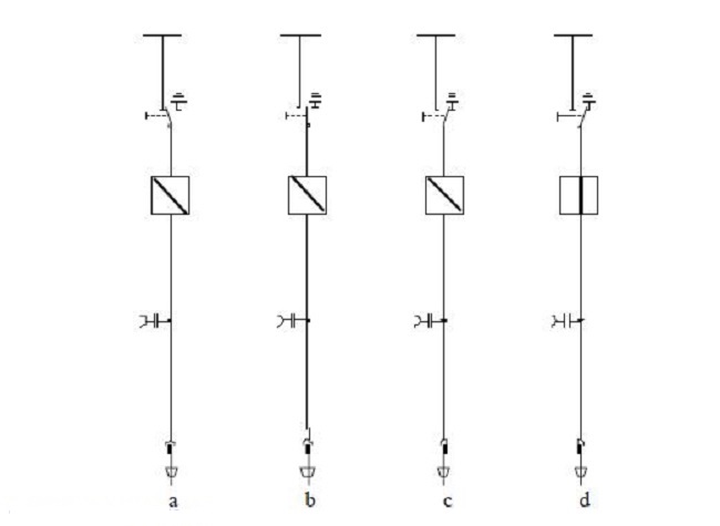
- The feeder circuit breaker is switched to the open position [see Figure(a)]. This unlocks the disconnect switch.
- The feeder disconnect switch is switched to the open position [see Figure(b)].Verify by viewing.
- The feeder is now isolated on bus side.
Sequence of operation for feeder grounding:
- Verify circuit is de energized by means of the integrated voltage detector/indicator.
- The grounding switch is switched to closed position [see Figure(c)]. Verify by viewing.
- Close the feeder circuit breaker [see Figure(d)].
- Lock feeder circuit breaker in closed position according to manufacturer’s O&M manual.
- The feeder is now grounded through the circuit breaker on the line side.
In figure shown switching arrange between breaker and earthing switch in a medium voltage GIS switchgear.


Thank you so much ,but let me had a question, for grounding feeder we should closing earth switch and C.B both of them, but if the C.B is open( is not close) what happen? i want to know the difference between Open & close C.B during Earth switch
I will appreciate your answers
best regard
Hello, if you mean to close the earth switch of GIS system: at that moment the CB must be open. In any case, the interlock between the CB and the earth switch will not allow the CB to close when the earth switch is closed.
Thanks