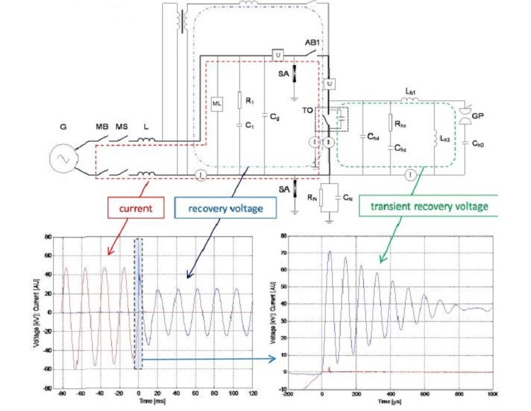
In synthetic test circuits, normally applied for high-voltage circuit-breaker testing, current is supplied
by a generator and (transient) recovery voltage is supplied by a pre-charged capacitor bank.
Whereas a capacitor bank of a synthetic circuit is very well suited to supply the adequate TRV, it cannot maintain an adequate recovery voltage for a sufficiently long time.
Basically, there are two possibilities to discharge these capacitors:
1. Maintain the remaining capacitor bank voltage as a unipolar (DC) voltage across the breaker. This is unrealistic, and stresses the test-object in a way very different from reality.
2. Realization of a damped oscillatory voltage by applying a large inductor across the capacitor bank.
Strong damping cannot be avoided in the circuit, even when inductors with a high quality factor are
applied.
In both cases, for general purpose circuit-breakers, IEC 62271-101 clause 4.1.3 allows recovery voltage to drop not lower than 50% of the rated phase-to-ground voltage after 100 ms. Although this is also not realistic, it is a generally accepted compromise.
For GCBs, recovery voltage to drop not lower than 50% of the rated phase-to-ground voltage after 100 ms.
In order to fulfill customer’s requirements of producing both GCB TRV as well as a constant power frequency recovery voltage, a new type of hybrid (single phase) circuit is developed :
- produce the required fault current
- produce TRVs of steepness adequate for GCB in IEEE C37.013 This property is very helpful in providing assurance of the dielectric strength of the breaker during the whole recovery phase (defined by IEC as 300 ms following interruption). Application of a constant recovery voltage eliminates discussion on possible dielectrical issues such as re-strikes and late breakdown;
- produce realistic, constant power frequency recovery voltages
- independent control of current, TRV and RV voltages in development tests
- realistic simulation of events occurring at re-strike. Upon re-strike, a large current is provided by the current circuit.
In figure the building blocks of the hybrid test-circuit are outlined, with the functionalities of each of the relevant parts: current circuit (red), TRV circuit (green) and RV circuit (red). Also shown are the real wave traces as realized in a GCB test with this circuit.
G: Short-circuit generators; MB: master breaker; MS: making switch; AB: aux breakers; TO: test GCB; PT: power transformer; ML: re-ignition installation; GP: triggered spark-gap;SA: surge arrester; R,L,C: resistor,reactor,capacitor; U, I: voltage-, current measurement


