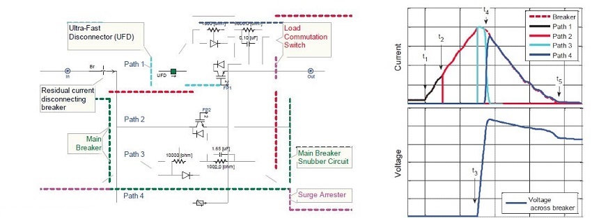
In hybrid breaker with electronic interruption by IGBTs simulink (left pic), the commutation of fault current from main path into the interrupter path is carried out by an IGBT in path 1,whereas local current zero is created by a stack of IGBTs in path 2.
In right pic the short circuit fault current starts to flow through the breaker at t1,then at t2 current is interrupted in path 1 that shown in left pic and the fault current commutates into path 2. Next, at t3, the current is interrupted in path 2, and commutates into path 3. Its high impedance leads to a steep rise of voltage, until the surge arrester limits that voltage at t4. This voltage is called transient interruption voltage (TIV). It is important to realize that, from this point on the system starts to recover, although the current in the fault location has not been interrupted yet. The faulted section is effectively separated from the healthy part of the system. From this point on, the voltage (above the rated system voltage) steadily reduces the current to zero; while the system’s inductive energy is dissipated in the arrester of path 4.


