



A generator circuit breaker (GCB) is a critical part of a power plant’s electrical system. Installed between the generator terminals and the generator step-up transformer, it allows the generating unit to be switched and isolated while providing protection against demanding electrical faults.
Selecting a GCB is not simply a matter of matching rated voltage, nominal current and a short-circuit breaking-current figure. A generator circuit is exposed to electrical conditions that differ from those encountered by an ordinary distribution circuit breaker. The generator and the interconnected power system can both contribute to fault current, while the source of the fault affects the current waveform and the transient recovery voltage across the breaker contacts.
For engineers preparing a new power plant, replacing an existing GCB or evaluating supplier proposals, the most useful starting point is a coordinated set of system studies, equipment requirements and acceptance criteria.
This guide sets out the main engineering considerations for specifying a generator circuit breaker and evaluating whether a proposed solution is suitable for the actual application.
1. Define the electrical arrangement before selecting the breaker
The first step is to establish exactly how the generator circuit is configured and how the plant is expected to operate.
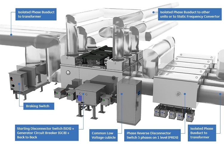
For a conventional generating unit, the GCB is normally installed on the generator side of the step-up transformer. However, the complete arrangement may include isolated-phase bus duct, a starting switch, an earthing switch, a disconnector, instrument transformers, surge arresters and connections to the station auxiliary supply.
The required arrangement varies with plant design. Pumped-storage installations, plants with multiple generators connected to one transformer and installations using special starting arrangements require particular attention.
Before requesting quotations, collect the following information:
- Generator rated voltage, MVA, power factor and rated current.
- Generator reactances and time constants needed for short-circuit calculations.
- Generator step-up transformer impedance, vector group and relevant nameplate data.
- Maximum and minimum network short-circuit levels, including the applicable X/R characteristics.
- Single-line diagrams showing the generator, GCB, transformer, bus ducts and associated switching equipment.
- Operating modes, including startup, synchronization, normal shutdown and any special switching sequences.
- Environmental conditions, installation altitude, ambient temperature and cooling requirements.
These are inputs to the application study, not substitutes for it. The equipment supplier should receive the relevant system-study results and clearly defined operating duties.
2. Evaluate both generator-source and system-source fault duties
One of the most important points in GCB selection is that generator-source and system-source short-circuit duties are not interchangeable.
A fault close to the generator terminals can be fed by the generator itself. A fault on the system side may receive a contribution from the interconnected grid through the step-up transformer. The prospective current and transient recovery voltage (TRV) depend on the fault location, the network configuration and the electrical parameters of the connected equipment.
The specification should therefore identify the applicable duties separately.
Generator Circuit Breaker Selection: A Practical Engineering Checklist
A generator circuit breaker (GCB) is a critical part of a power plant’s electrical system. Installed between the generator terminals and the generator step-up transformer, it allows the generating unit to be switched and isolated while providing protection against demanding electrical faults.
Selecting a GCB is not simply a matter of matching rated voltage, nominal current and a short-circuit breaking-current figure. A generator circuit is exposed to electrical conditions that differ from those encountered by an ordinary distribution circuit breaker. The generator and the interconnected power system can both contribute to fault current, while the source of the fault affects the current waveform and the transient recovery voltage across the breaker contacts.
For engineers preparing a new power plant, replacing an existing GCB or evaluating supplier proposals, the most useful starting point is a coordinated set of system studies, equipment requirements and acceptance criteria.
This guide sets out the main engineering considerations for specifying a generator circuit breaker and evaluating whether a proposed solution is suitable for the actual application.
1. Define the electrical arrangement before selecting the breaker
The first step is to establish exactly how the generator circuit is configured and how the plant is expected to operate.
For a conventional generating unit, the GCB is normally installed on the generator side of the step-up transformer. However, the complete arrangement may include isolated-phase bus duct, a starting switch, an earthing switch, a disconnector, instrument transformers, surge arresters and connections to the station auxiliary supply.
The required arrangement varies with plant design. Pumped-storage installations, plants with multiple generators connected to one transformer and installations using special starting arrangements require particular attention.
Before requesting quotations, collect the following information:
- Generator rated voltage, MVA, power factor and rated current.
- Generator reactances and time constants needed for short-circuit calculations.
- Generator step-up transformer impedance, vector group and relevant nameplate data.
- Maximum and minimum network short-circuit levels, including the applicable X/R characteristics.
- Single-line diagrams showing the generator, GCB, transformer, bus ducts and associated switching equipment.
- Operating modes, including startup, synchronization, normal shutdown and any special switching sequences.
- Environmental conditions, installation altitude, ambient temperature and cooling requirements.
These are inputs to the application study, not substitutes for it. The equipment supplier should receive the relevant system-study results and clearly defined operating duties.
2. Evaluate both generator-source and system-source fault duties
One of the most important points in GCB selection is that generator-source and system-source short-circuit duties are not interchangeable.
A fault close to the generator terminals can be fed by the generator itself. A fault on the system side may receive a contribution from the interconnected grid through the step-up transformer. The prospective current and transient recovery voltage (TRV) depend on the fault location, the network configuration and the electrical parameters of the connected equipment.
The specification should therefore identify the applicable duties separately.
| Engineering consideration | What the designer should establish |
|---|---|
| Generator-source short-circuit duty | The calculated generator contribution, its AC component, asymmetry and relevant contact-separation conditions |
| System-source short-circuit duty | The grid contribution through the transformer, based on the applicable network fault level and impedance characteristics |
| Peak making current | The peak current associated with the specified closing duty |
| Short-time withstand | The required current withstand level and duration for the applicable equipment |
| Transient recovery voltage | The relevant TRV envelope, including peak voltage, rate of rise and other applicable parameters |
| Out-of-phase duty | Whether the operating and protection philosophy requires the breaker to interrupt a fault under the specified out-of-phase conditions |
| Switching duties | Relevant load-current, capacitive-current or other special switching conditions identified by the study |
The engineering team should not assume that a breaker with an apparently adequate symmetrical short-circuit rating will automatically satisfy every generator-circuit duty.
TRV deserves particular attention. It is the voltage that develops across the breaker contacts after current interruption and is part of the interruption duty the equipment must withstand. Circuit capacitance, including relevant bus and associated equipment capacitance, can affect the prospective TRV. The applicable standard, system study and manufacturer’s type-test evidence should be considered together.
For additional background, see the existing Switchgear Content articles on GCB breaking-capacity classification and source short-circuit current definitions.
3. Use the applicable generator circuit-breaker standard
The principal international reference for the application covered by this guide is IEC/IEEE 62271-37-013, High-voltage switchgear and controlgear — Part 37-013: Alternating current generator circuit-breakers.
The applicable corrected edition should be identified in the project specification. The IEC currently lists the 2021 edition with a corrected version dated June 2025. Its scope covers three-phase AC generator circuit-breakers designed for indoor or outdoor installation, operating at 50 Hz or 60 Hz, above 1 kV and up to 38 kV.
The standard also addresses the generator circuit-breaker system and specific configurations, including multiple generators connected to one step-up transformer, tee-off arrangements and particular pumped-storage and wind-farm applications.
Requirements for generators and transformers rated below 10 MVA and for pumped-storage installations need special consideration; the standard does not cover every such application completely. The project team should establish the required compliance basis rather than assume that a standard reference alone settles the engineering requirements.
Reference: IEC/IEEE 62271-37-013 — official IEC publication.
4. Prepare a complete GCB technical specification
A useful specification allows different suppliers to respond to the same electrical duties and project boundaries. It should state both the required performance and the evidence expected to demonstrate compliance.
The following checklist can be used when preparing a technical datasheet or reviewing a tender.
| Specification section | Information to include |
|---|---|
| Project and generator | Generator MVA, rated voltage, frequency, rated current and operating arrangement |
| Rated electrical characteristics | Rated maximum voltage, insulation requirements, continuous-current duty and applicable site conditions |
| Short-circuit performance | Separate generator-source and system-source duties, associated asymmetry requirements, making current and short-time withstand requirements |
| TRV and special duties | Applicable TRV requirements, out-of-phase duty and other switching duties identified by the study |
| Operating mechanism | Required opening and closing performance, operating sequence, control supply and relevant mechanical requirements |
| Protection and control | Trip and close circuits, required auxiliary contacts, status indications, control logic, interlocking and interfaces with plant automation |
| Associated equipment | Scope of disconnectors, earthing switches, starting switches, CTs, VTs, surge arresters and local control equipment, as applicable |
| Environment and cooling | Indoor or outdoor installation, ambient temperature, altitude, enclosure conditions and cooling arrangements |
| Standards and verification | Applicable standard and edition, relevant type-test evidence, routine-test requirements and project acceptance criteria |
| Supply and maintenance | Drawings, manuals, spare parts, special tools, training, maintenance requirements and long-term service arrangements |
A simple but important rule applies: every required function must have a clearly defined scope and a means of verification.
For example, if an integrated disconnector or earthing switch is required, identify its duties, interlocking requirements, position indication and test documentation. Do not leave the supplier to infer whether it belongs to the GCB package or another part of the installation.
Likewise, state the control-system interface explicitly. If the plant uses IEC 61850, Modbus TCP or another interface, specify the required protocol, signals and integration responsibilities. These interfaces must be confirmed for the proposed model rather than assumed from a manufacturer’s general product portfolio.
5. Coordinate the GCB with the protection and control system
A generator circuit breaker operates within a coordinated protection scheme. Its specification should therefore be reviewed alongside the generator protection, transformer protection, bus protection and associated control logic.
Depending on the plant design, the relevant functions may include generator differential protection (87G), transformer differential protection (87T), breaker-failure protection (50BF), synchronism checking (25) and lockout logic (86).
The actual protection arrangement and trip matrix must be established by the project’s protection engineers. The presence of a particular relay function does not, by itself, establish the correct trip destination or operating sequence.
The design review should address the following questions:
- Which initiating protection functions are intended to trip the GCB?
- How are generator tripping, excitation-system tripping, and prime-mover shutdown coordinated?
- What actions are required if the GCB fails to interrupt a fault?
- What synchronism-check and closing interlocks apply?
- How are trip-circuit supervision, control-power failure, and breaker-position feedback handled?
- Are all required signals and indications available to the plant control system?
A trip matrix and control schematic should be reviewed by the responsible engineering parties before the equipment design is finalized. Changes to the generator, transformer or plant operating philosophy may require the protection and control interfaces to be revisited.
6. Plan verification and commissioning before delivery
Commissioning should not be treated as a task that begins when the breaker arrives on site. The acceptance requirements should be agreed during procurement, with a clear distinction between design qualification, routine production checks, factory acceptance activities and site commissioning.
The project should identify which documents and results are required from the supplier, including the relevant type-test evidence for the offered design and ratings.
The commissioning plan should address, as applicable:
- Inspection for transport damage and verification of the installed equipment against the approved drawings.
- Correct mechanical assembly and operation, using the manufacturer’s approved procedures.
- Verification of opening and closing performance, including applicable pole timing and pole-to-pole spread requirements.
- Checks of auxiliary contacts, interlocks, control circuits, trip circuits and position indications.
- Electrical test results required by the approved commissioning specification.
- Examination of the operating mechanism and associated monitoring functions.
- Insulating-gas checks and leak-monitoring provisions, where applicable to the selected design.
- Verification of protection interfaces, alarms and end-to-end control logic.
For practical background on timing measurements, refer to Verification of time quantities in GCB commissioning tests.
All tests and acceptance decisions should follow the applicable standards, the approved project procedures and the manufacturer’s instructions, performed by appropriately qualified personnel. A general checklist does not replace model-specific procedures or site safety requirements.
7. Plan maintenance around condition, duty and manufacturer requirements
A maintenance programme should reflect the specific breaker design, its operating duty and the manufacturer’s instructions. Applying a generic maintenance interval without considering actual service conditions can miss relevant deterioration or lead to unnecessary intervention.
Useful records include:
- Operating counts and recorded switching events.
- Opening and closing performance trends.
- Operating-mechanism condition and any changes in charging or operating behaviour.
- Contact-condition information obtained through the manufacturer’s recommended inspection methods.
- Insulating-gas density, leakage and other relevant condition indicators, where applicable.
- Alarm history, trip-circuit supervision and monitoring-system records.
- Inspection findings, corrective work and replaced components.
Contact resistance is useful information, but a satisfactory measurement should not automatically be treated as proof that the main contacts are healthy. The appropriate interpretation depends on the breaker design and the manufacturer’s defined inspection criteria. Some designs permit direct visual inspection of relevant contact components; others require different condition-assessment methods.
The plant should retain commissioning baselines and compare subsequent results against appropriate limits and trends. Where the installed GCB has condition monitoring, specify which measurements and alarms are available, how they are retained, and who is responsible for reviewing them.
8. Common specification mistakes to avoid
Several recurring problems can be reduced by reviewing the application study and purchase specification together.
Selecting on short-circuit current alone. A single symmetrical current figure does not describe every required interruption duty. Confirm source-specific duties, relevant asymmetry, TRV and special switching requirements.
Using the wrong system configuration. Calculations based on an incomplete single-line diagram may not represent alternative operating modes, multiple-generator connections or special startup arrangements.
Leaving accessory scope unclear. Establish the boundaries for disconnectors, earthing switches, instrument transformers, control cubicles, monitoring systems and bus connections.
Ignoring site conditions. Continuous-current capability and cooling provisions must be appropriate to the actual installation conditions. Do not select a product from its maximum brochure rating without checking the conditions attached to that rating.
Accepting a generic compliance statement. Ask suppliers to identify the offered design, its applicable ratings and the supporting test documentation. Confirm that the supplied configuration corresponds to the evidence.
Treating commissioning as a timing test alone. Mechanical, electrical, control, protection and auxiliary-system requirements must all be covered by the approved acceptance plan.
9. A practical checklist for a GCB request for quotation
Before issuing an RFQ, confirm that the enquiry package contains the following:
- Approved single-line diagram and a description of all relevant operating modes.
- Generator and step-up transformer data, including the parameters required for short-circuit studies.
- Network short-circuit data and the applicable results at the GCB location.
- Separate generator-source and system-source duty requirements, plus relevant TRV and special switching requirements.
- Required voltage, continuous current, insulation levels, short-circuit ratings and environmental conditions.
- Defined scope of associated switching equipment, instrumentation, protection interfaces and control systems.
- Required standard and edition, supplier compliance schedule, deviations and applicable type-test evidence.
- Factory and site acceptance requirements, technical documentation, maintenance information and spare-parts arrangements.
Require each bidder to complete the same technical schedule. Any exceptions should be listed explicitly, with their engineering implications explained. This makes technical evaluation more meaningful than comparing headline current ratings or brochure descriptions.
Frequently asked questions
What makes a generator circuit breaker different from a conventional circuit breaker?
A GCB must meet the duties associated with a generator circuit, including the relevant generator-source and system-source short-circuit conditions and transient recovery voltage requirements. Its suitability cannot be established solely from a rating commonly used for a conventional feeder breaker.
Which standard should be referenced in a GCB specification?
IEC/IEEE 62271-37-013 is the principal international reference for the AC generator circuit-breakers within its scope. The project specification should identify the applicable corrected edition and address any special application conditions that require additional consideration.
Can an existing GCB be replaced with a breaker having the same nominal ratings?
Matching the nameplate ratings is not sufficient on its own. A replacement assessment should also consider the short-circuit and TRV duties, installation geometry, bus connections, control interfaces, associated switching equipment and required test evidence.
What should be compared when evaluating GCB manufacturers?
Compare the specific offered model against the same application requirements: applicable ratings, documented fault duties, type-test evidence, accessory scope, operating mechanism, cooling arrangements, monitoring features, installation constraints, maintenance needs and lifecycle support. A general manufacturer comparison is useful for initial research but cannot replace project-specific verification.
Conclusion
A reliable generator circuit breaker selection begins with the power system, not the product catalogue. The engineering team should establish the operating arrangement, calculate the applicable fault duties, define the required electrical performance and coordinate protection, controls and commissioning requirements before finalizing the purchase specification.
A complete datasheet, consistent bidder responses and clear verification criteria help reduce technical ambiguity and make the selection process more defensible. The same discipline should continue through factory acceptance, site commissioning and lifecycle maintenance.
Engineering note: Final equipment selection and acceptance must be based on the project-specific studies, applicable standards, approved procedures and the selected manufacturer’s technical documentation.