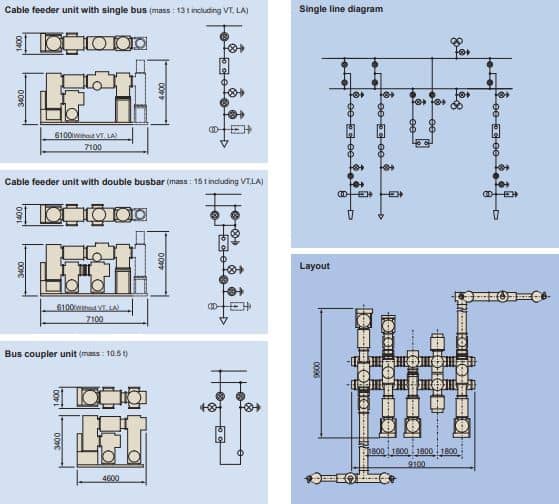
Photo source from Fuji Electric GIS catalog just for show
Typical Gas Insulated Switchgear (GIS) Layout description:
Operational requirements and reliability of the power system are major aspects used to determine the gas-insulated switchgear layout. In addition, future extensions, service, and maintenance considerations are well as investment costs will contribute to enabling a decision to be made for a suitable substation layout. The following arrangements show common layouts used for Gas Insulated Switchgear (GIS) substations.
1- Single bus arrangement gas insulated switchgear layout:
When substation reliability is not the main request the single bus arrangement has the lowest investment needed to design a GIS substation. This may be the case for small substations in relatively unimportant sections where limitations to operational requirements and maintenance activities can be accepted. The substation would be affected by an outage in the case of busbar failures and service or maintenance activities. A single bus bar arrangement of a three-phase insulated GIS is shown in Figure 1.

Figure1: Single bus arrangement gas insulated switchgear layout
2- Double bus arrangement gas insulated switchgear layout:
Operation flexibility and reliability are higher by extending the arrangement by a second bus bar when selecting the double bus arrangement. For important network points, the higher investment allows the substation to be operated with two bus bars that are coupled via a tie breaker.
Each feeder is connected to the two bus bars. Maintenance can be done on one bus bar while the other bus bar stays in service. A double bus bar arrangement of a three-phase insulated GIS is shown in Figure 2.
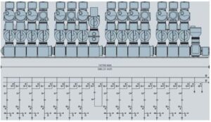
Figure 2: Double bus arrangement gas insulated switchgear layout
3- Ring bus arrangement gas insulated switchgear layout:
In a ring bus arrangement, the GIS bays are arranged in a ring, which provides good reliability at moderate costs since there is no extra bus bar. In case of a failure in one bus section, only the circuit in that bus section will be affected, and the other circuits can remain in service.
Performing maintenance on one GIS breaker can be done by isolating this bus section and keeping the other bus sections in operation. A ring bus bar arrangement of a three-phase insulated GIS is shown in Figure 3 The ring arrangement typically involves about six GIS feeders and is limited to extensions.
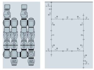
Figure 3:Ring bus arrangement gas insulated switchgear layout
4-H-Scheme arrangement gas insulated switchgear layout:
The H-scheme can be described as two single bus sections that are coupled by a center circuit breaker. In comparison with the single bus arrangement, the H-scheme provides higher reliability but also higher costs due to additional circuit breakers. In case of a breaker failure, the complete substation would not be out of service. Maintenance of one feeder can be done while the other feeders stay in operation. An H-scheme arrangement of a three-phase insulated GIS is shown in Figure 4.
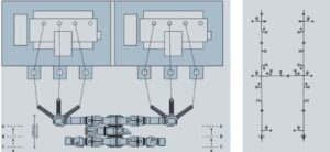
Figure 4:H-Scheme arrangement gas insulated switchgear layout
5-Breaker and a half arrangement gas insulated switchgear layout:
With a relatively high investment, the breaker-and-a-half arrangement ensures very high reliability. Even in the event that one bus bar would fail the power supply of feeders will be kept in service. A breaker-and-a-half arrangement of a single-phase insulated GIS is shown in Figure 5 This layout allows flexible operation. Any breaker can be isolated, for example, for maintenance or service work, while the other feeders can still be operated. The two bus bars are energized under regular operating conditions. As a name for this layout, there are one and a half breakers per circuit. Three circuit breakers are designed for two circuits where each circuit shares the circuit breaker in the center.
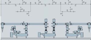
Figure 5: Breaker and a half arrangement gas insulated switchgear layout


Hello Ali,
is this website still active
Hi
Thanks for your comment.
Please connect with me for any request.