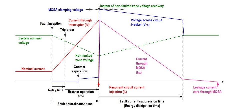
Current and voltage wave forms are given in Figure. The opening sequence starts when the DCCB is in normal operation(interrupter S1 and Residual current circuit breaker S2 are closed, S3 is open).
The CB is triggered by the protection relay. A 2ms relay time has been assumed here. After the trip signal has been received,s switch S1 begins to actuate. When it has reached a sufficient distance(to withstand the transient voltage applied during interruption) the resonant circuit injects a counter-current, by closing switch S3. This generates a current zero within the interrupter(S1)and all current now flows through the resonant branch, causing capacitor voltage to rise. When the clamping voltage of the SA is reached current through the circuitbreaker begins to rapidly decrease.
The total time from the trip signal being received to counter voltage generation is approximately 8ms, which takes into account mechanical actuation and current commutation, etc.
Energy stored in the system is then dissipated in the SA.
on system conditions.
S1: High speed mechanical interrupter
S2: Residual current circuit breaker
S3: High speed switch
SA: Surge arrester


