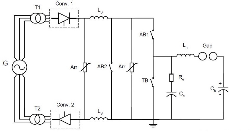
A 12-pulse rectifier is used as the current source to supply the DC test current and a voltage oscillation circuit is used to supply the recovery voltage after current switching. An auxiliary circuit breaker and a spark gap are implemented in the circuit to connect these two sources to the test object at specific time interval. Description of the figure:
- The 12-pulse rectifier is controlled to generate a DC test current to the test breaker (TB) through smoothing reactor (Ls) and auxiliary breaker (AB1) at a relative low generator driving voltage.
- AB1 and TB open simultaneously and DC current arcs are established inside the interrupting chambers of these breakers
- Spark gap in the voltage circuit is ignited at the instant that the arcing time of TB will be equal to the prospected value
- AB2 closes and bypasses the DC current
- AB1 clears as the DC current transfer from AB1 – TB branch to AB2 bypass branch
- TB is stressed by the injection current alone from the voltage circuit after AB1 clears
- TB clears at injection current zero crossing and withstands a transient recovery voltage and subsequent DC voltage afterwards
- DC source rectifier’s is blocked by stopping firing signal sending


